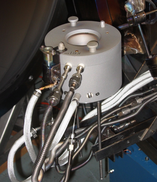
Varian Cary 5000 Spectrophometer
The following figure is intended to help debug problems with our unit, which
have plagued us for the past 1-2 years (click on image for PDF):
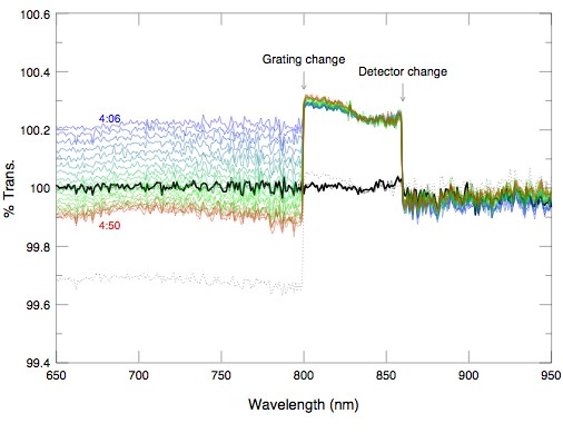
These data were collected over the space of about 55 minutes. The unit had
been on for about 5 hours, so it should have been stable. One bare
quartz slide was placed in each of the sample and reference beams, in
transmission, a baseline taken, and then a regular transmission trace.
The heavy black line shows the result,
at 100% transmission as expected (a second thin solid black line shows a
repetition, hard to see as it falls under the heavy line). The sample
compartment was opened and the slide in the sample beam reversed. The colored
lines show the progression from 4:06 to 4:50 pm. Then the sample compartment
was opened and the sample slide reversed again, ie, restored to its original
orientation. The resulting trace is shown as the black dotted line. Except
for reversing the sample slide twice, the unit was not touched or changed
in any way. Three zones are present in the traces:
IR detector/IR grating:
This zone (redward of 860nm) is relatively stable. There is a slight
drift with time, at a reasonable level for PbS detectors.
Vis detector/IR grating:
800-860 nm.
The only difference from the previous zone is a detector change.
Reversing the slide produced a significant step; returning it to the
original position removed the step. This means that the UV-Vis detector is
incredibly sensitive to alignment, as a small change in the optics in the
path produces a large change in measured intensity.
Note that this optical change does not affect the PbS detector, which is small
and therefore highly sensitive to alignment,
so the introduced optical change must be very small.
Vis detector/Vis grating:
800 nm blueward.
The only difference from the previous zone is a grating change. The
obvious pattern here is a monotonic drift with time. This must be related to
the UV-Vis grating, as it is the only difference. We speculate
that the alignment is changing, and because the UV_Vis detector is so
sensitive to alignment, the small grating alignment drift results in a
significant drift in measured intensity level.
UPDATE (sort of):
The Varian Sales Rep presponded to this data by making a visit,
the first input from Varian since we notified them directly (rather than
through Service) in June 2006. During the visit, he observed the drift.
He stated this was clearly wrong. That was Oct.4. It is now Nov. 20. There has
been absolute silence from Varian in the interim.
Has the problem gone away? Check out this
baseline drift over 30 minutes. The blue curve was taken immediately after
a baseline, and the drift was monotonic.
The scan has the same parameters as the one above. Interestingly,
in this case both the IR and Vis are drifting, unlike the last figure.
A couple of days ago, we did some reflectance measurements, followed by a
straight-through base-line configuration. The step in the "100%" line was 1.5%
at 800 nm. Since we are trying to measure reflectance at the 0.1% level, we're
clearly being hobbled by this instrument. Varian has been told this repeatedly.
And, yes, we are under service contract with them.
UPDATE (Jan. 07): The unit was serviced in early Decemeber, and it
was found to be out of alignment. The step in transmission was reduced to
<= 0.1% in transmission. In reflectance, we are still seeing some apparent
drift, now on the IR side, leading to steps up to 0.3%. This has not been
well-characterized, though, and may be the standard "noise" in the reflectance
mode. In general, the unit appears usuable again.
Last modified: 20jan2007
Andrew C. Phillips / Lick Observatory
phillips@ucolick.org