ESI Spectrograph Electronics Manual
![]()
![]()
![]()
Wiring:
The wiring section of the manual contains the descriptions of the various stage schematics for the Eshelette Spectrograph and Imager, ESI. It corresponds to the wiring tab in the electronics schematics binder.
Slit Mask Wheel Stage Wiring, EL-3350 sheets 1 and 2, and EL-3351
Simplified Stage Diagram
The EL-3350 and EL-3351 schematics show the wiring of the Slit Mask stage. The Filter Wheel and the Aperture Wheel stages are wired identically with the exception of the pin numbers with which they connect to the Galil controller. The connections at the Galil are explained in the Signals section of this manual.
Looking at sheet 1 of EL-3350, the right-hand edge of the schematic shows the servo motor and it's encoder. In the middle of the drawing are representations of the EL-1238 Stage Interconnect Box (inside the dashed lines) and the Galil amplifier mounted connector panel. The left side of the drawing shows the the Galil controller and amplifier. The servo motor is a standard Galil 50-1000 motor. It is rated at 10.8 oz-in/A (30 oz-in peak) of torque and it's encoder has 1000 counts in quadrature that the controller decodes to 4000 counts per revolution. In the case of the three wheel stages, the motor encoder is wired to the auxiliary encoder input on the Galil controller. This indicates that the stage is using dual-loop encoding. The stage interconnect box wiring swaps the motor encoder signals with the Renishaw linear encoder signals so that the servo loop is closed around the Renishaw encoder in stead of the motor encoder. (also see EL-3351).
Unlike most other stages, the Slit Mask Stage uses an magnetic index to generate the HOME signal. As this is an unconstrained rotating stage, the primary and secondary FWD and REV limits are not implemented. With the magnetic fiducial, the software can search for the edge of the 'Home' flag to zero out the encoder count buffer. The process is actually a little more involved then this and is covered in the Introduction section.
The EL-1238 stage interconnect box is wired to pass the position information and motor power. The power for the motor is wired to two sets of twisted pairs in the stage cable between the Galil amplifier connection panel and the stage interconnect box. The twisted pairs are AWG 22-gauge wire. The two pairs are tied together at the terminals in the EL-1238 box and AWG 18-gauge wires connect to the motor via pins 1 and 2 of JB2.
The 10-pin flat ribbon cable from the servo motor encoder connects directly to an EL-2260 encoder buffer board that is mounted inside the interconnect box. (This is the same board is used in DEIMOS and HIRES). Unfortunately, to disconnect this cable the cover has to be removed from the box. The power for this board comes from the logic supply mounted on the Galil controller mounting plate. The +5V and ground are routed to the EL-1238 box via pins 11 and 12. The output of the encoder buffer board is connected to the terminal strip inside of the interconnect box by a 10-pin flat ribbon cable. In the case of the dual-loop encoded stages, the motor encoder signals leave the interconnect box via JB5 and connect to the Galil amplifier connector panel via the auxiliary encoder input at J21.
At the top center of sheet 1 are connections to the logic power supply. These are all wired inside the connector panel from pins on the stage cable connectors to pins on the large connector J10 with black and red wires. These wires come from the long terminal strips on the Galil panel. From there the go to the logic power supply. Next to the logic power supply connections is the connection from the Lambda +28V power supply. This is the power that is supplied to the amplifiers to run the servo motors. On the left side of the drawing is the controller box. The connections shown between the controller and the amplifier are made through flat ribbon cables.
EL-3350 Sheet 2 specifies cables and connectors used on each of the motor driven stages.
EL-3351 Slit Mask Stage Encoder Wiring
Simplified Encoder Diagram
This drawing shows the wiring for the Renishaw linear encoder. The Renishaw encoder is used to close the servo loop for the wheel and collimator stages. The encoder is on the right side of the sheet. Next to it is the stage interconnect box for this stage - this is the same box shown on the EL-3350 schematic. The encoder cable attaches to the box via the DB15 connector JB4. The signals are then split up to go to the Galil controller via the stage cable J1 and the auxiliary encoder cable via J21. The Renishaw encoder signals are wired to the axis motor encoder inputs to close the servo loop. The power for the encoder is supplied by connections to the logic supply through J10 pins 49 and 17.The index signal is wired to the HOMEA input for this axis.
Filter Wheel Stage Wiring, EL-3352, and Encoder Wiring, EL-3353
Simplified Stage Diagram
The EL-3352 and EL-3353 schematics show the wiring of the Filter Wheel stage. The Slit Mask and the Aperture Wheel stages are wired identically with the exception of the pin numbers with which they connect to the Galil controller. The connections at the Galil are explained in the Signals section of this manual.
Looking at EL-3352, the right-hand edge side of the schematic shows the servo motor and it's encoder. In the middle of the drawing are representations of the EL-1238 Stage Interconnect Box (inside the dashed lines) and the Galil amplifier mounted connector panel. The left side of the drawing shows the the Galil controller and amplifier. The servo motor is a standard Galil 50-1000 motor. It is rated at 10.8 oz-in/A (30 oz-in peak) of torque and it's encoder has 1000 counts in quadrature that the controller decodes to 4000 counts per revolution. In the case of the three wheel stages, the motor encoder is wired to the auxiliary encoder input on the Galil controller. This indicates that the stage is using dual-loop encoding. The stage interconnect box wiring swaps the motor encoder signals with the Renishaw linear encoder signals so that the servo loop is closed around the Renishaw encoder in stead of the motor encoder. (also see EL-3353).
Unlike most other stages, the Filter Wheel Stage uses an magnetic index to generate the HOME signal. As this is an unconstrained rotating stage, the primary and secondary FWD and REV limits are not implemented. With the magnetic fiducial, the software can search for the edge of the 'Home' flag to zero out the encoder count buffer. The process is actually a little more involved then this and is covered in the Introduction section.
The EL-1238 stage interconnect box is wired to pass the position information and motor power. The power for the motor is wired to two sets of twisted pairs in the stage cable between the Galil amplifier connection panel and the stage interconnect box. The twisted pairs are AWG 22-gauge wire. The two pairs are tied together at the terminals in the EL-1238 box and AWG 18-gauge wires connect to the motor via pins 1 and 2 of JB2.
The 10-pin flat ribbon cable from the servo motor encoder connects directly to an EL-2260 encoder buffer board that is mounted inside the interconnect box. (This is the same board is used in DEIMOS and HIRES). Unfortunately, to disconnect this cable the cover has to be removed from the box. The power for this board comes from the logic supply mounted on the Galil controller mounting plate. The +5V and ground are routed to the EL-1238 box via pins 11 and 12. The output of the encoder buffer board is connected to the terminal strip inside of the interconnect box by a 10-pin flat ribbon cable. In the case of the dual-loop encoded stages, the motor encoder signals leave the interconnect box via JB5 and connect to the Galil amplifier connector panel via the auxiliary encoder input at J22.
At the top center of sheet 1 are connections to the logic power supply. These are all wired inside the connector panel from pins on the stage cable connectors to pins on the large connector J10 with black and red wires. These wires come from the long terminal strips on the Galil panel. From there the go to the logic power supply. Next to the logic power supply connections is the connection from the Lambda +28V power supply. This is the power that is supplied to the amplifiers to run the servo motors. On the left side of the drawing is the controller box. The connections shown between the controller and the amplifier are made through flat ribbon cables.
EL-3353 Filter Wheel Stage Encoder Wiring
Simplified Encoder Diagram
This drawing shows the wiring for the Renishaw linear encoder. The Renishaw encoder is used to close the servo loop for the wheel and collimator stages. The encoder is on the right side of the sheet. Next to it is the stage interconnect box for this stage - this is the same box shown on the EL-3352 schematic. The encoder cable attaches to the box via the DB15 connector JB4. The signals are then split up to go to the Galil controller via the stage cable J2 and the auxiliary encoder cable via J22. The Renishaw encoder signals are wired to the axis motor encoder inputs to close the servo loop. The power for the encoder is supplied by connections to the logic supply through J10 pins 48 and 18.The index signal is wired to the HOMEB input for this axis.
Aperture Wheel Stage Wiring, EL-3354, and Encoder Wiring, EL-3355
Simplified Stage Diagram
The EL-3354 and EL-3355 schematics show the wiring of the Aperture Wheel stage. The Slit Mask and the Filter Wheel stages are wired identically with the exception of the pin numbers with which they connect to the Galil controller. The connections at the Galil are explained in the Signals section of this manual.
Looking at EL-3354, the right-hand edge of the schematic shows the servo motor and it's encoder. In the middle of the drawing are representations of the EL-1238 Stage Interconnect Box (inside the dashed lines) and the Galil amplifier mounted connector panel. The left side of the drawing shows the the Galil controller and amplifier. The servo motor is a standard Galil 50-1000 motor. It is rated at 10.8 oz-in/A (30 oz-in peak) of torque and it's encoder has 1000 counts in quadrature that the controller decodes to 4000 counts per revolution. In the case of the three wheel stages, the motor encoder is wired to the auxiliary encoder input on the Galil controller. This indicates that the stage is using dual-loop encoding. The stage interconnect box wiring swaps the motor encoder signals with the Renishaw linear encoder signals so that the servo loop is closed around the Renishaw encoder in stead of the motor encoder. (also see EL-3355).
Unlike most other stages, the Aperture Wheel Stage uses an magnetic index to generate the HOME signal. As this is an unconstrained rotating stage, the primary and secondary FWD and REV limits are not implemented. With the magnetic fiducial, the software can search for the edge of the 'Home' flag to zero out the encoder count buffer. The process is actually a little more involved then this and is covered in the Introduction section.
The EL-1238 stage interconnect box is wired to pass the position information and motor power. The power for the motor is wired to two sets of twisted pairs in the stage cable between the Galil amplifier connection panel and the stage interconnect box. The twisted pairs are AWG 22-gauge wire. The two pairs are tied together at the terminals in the EL-1238 box and AWG 18-gauge wires connect to the motor via pins 1 and 2 of JB2.
The 10-pin flat ribbon cable from the servo motor encoder connects directly to an EL-2260 encoder buffer board that is mounted inside the interconnect box. (This is the same board is used in DEIMOS and HIRES). Unfortunately, to disconnect this cable the cover has to be removed from the box. The power for this board comes from the logic supply mounted on the Galil controller mounting plate. The +5V and ground are routed to the EL-1238 box via pins 11 and 12. The output of the encoder buffer board is connected to the terminal strip inside of the interconnect box by a 10-pin flat ribbon cable. In the case of the dual-loop encoded stages, the motor encoder signals leave the interconnect box via JB5 and connect to the Galil amplifier connector panel via the auxiliary encoder input at J23.
At the top center of sheet 1 are connections to the logic power supply. These are all wired inside the connector panel from pins on the stage cable connectors to pins on the large connector J10 with black and red wires. These wires come from the long terminal strips on the Galil panel. From there the go to the logic power supply. Next to the logic power supply connections is the connection from the Lambda +28V power supply. This is the power that is supplied to the amplifiers to run the servo motors. On the left side of the drawing is the controller box. The connections shown between the controller and the amplifier are made through flat ribbon cables.
EL-3355 Aperture Wheel Stage Encoder Wiring
Simplified Encoder Diagram
This drawing shows the wiring for the Renishaw linear encoder. The Renishaw encoder is used to close the servo loop for the wheel and collimator stages. The encoder is on the right side of the sheet. Next to it is the stage interconnect box for this stage - this is the same box shown on the EL-3354 schematic. The encoder cable attaches to the box via the DB15 connector JB4. The signals are then split up to go to the Galil controller via the stage cable J3 and the auxiliary encoder cable via J23. The Renishaw encoder signals are wired to the axis motor encoder inputs to close the servo loop. The power for the encoder is supplied by connections to the logic supply through J10 pins 48 and 18.The index signal is wired to the HOMEC input for this axis.
TV Focus Stage Wiring, EL-3356
Simplified Stage Diagram
The EL-3356 shows the TV Focus Stage Wiring. The TV focus stage is wired as a normal constrained motion stage using a single encoder. The connections at the Galil are explained in the Signals section of this manual.
Looking at EL-3356, the upper right side of the schematic shows the servo motor and it's encoder. In the middle of the drawing are representations of the EL-1236 Stage Interconnect Box (inside the dashed lines) and the Galil amplifier mounted connector panel. The left side of the drawing shows the the Galil controller and amplifier. The servo motor is a standard Galil 50-1000 motor. It is rated at 10.8 oz-in/A (30 oz-in peak) of torque and it's encoder has 1000 counts in quadrature that the controller decodes to 4000 counts per revolution. In the stage, the motor encoder is wired to the normal encoder input on the Galil controller. This indicates that the stage is using single-loop encoding. The stage interconnect box wiring sends the motor encoder signals directly to the Galil controller.
Like other stages, the TV Focus Stage uses an optical interrupter to generate the HOME signal and mechanical primary and secondary limit switches. The HOME optical interrupter is wired to the HOME input of the controller via the interconnect box and J4. The software enables the optical interrupter by asserting the FIDUCIAL ENABLE signal before any movement is permitted. The output signal OUT4 is pulled low to enable the interrupter. The primary limits are shown at the lower right-hand side of the drawing. These are wired via the interconnect box and J4 of the amplifier connector panel to the FLSD (Forward Limit Switch channel D) and RLSD inputs of the Galil controller. Their function is to tell the controller to stop motion in either the forward or reverse direction. If either of the limits are reached, the Galil controller ramps down and stops the motion of the stage. At this point, you can back out of the limits but you can't go further in the direction of the limit. The primary and secondary limits can only be reached if for some reason the software limits fail.
The secondary limits are shown at the upper right-hand side of the page. They are DPDT switches that both remove power from the motor and signal the controller that they have been reached. These are the final limits in the system and if the stage moves far enough to trip them the stage must be moved out of the limit by hand. One set of contacts is used to break the motor current path while the other set is wired in parallel to tell the controller that the stage has hit a limit. Direction information can be obtained from the primary limit switches.
Collimator Focus Motor #1 Stage Wiring , EL-3358 sheets 1 and 2, and EL-3359
Simplified Stage Diagram
The EL-3358 and EL-3359 schematics show the wiring of one of three collimator actuator motors. The other two are wired identically with the exception of the pin numbers with which they connect to the Galil controller. The connections at the Galil are explained in the Signals section of this manual.
Looking at sheet 1 of EL-3358, the right-hand edge of the schematic shows the servo motor and it's encoder. In the middle of the drawing are representations of the EL-1238 stage interconnect box (inside the dashed lines) and the Galil amplifier mounted connector panel. The left side of the drawing shows the the Galil controller and amplifier. The servo motor is a standard Galil 50-1000 motor. It is rated at 10.8 oz-in/A (30 oz-in peak) of torque and it's encoder has 1000 counts in quadrature that the controller decodes to 4000 counts per revolution. In the case of the collimator actuators, the motor encoder is wired to the auxiliary encoder input on the Galil controller. This indicates that the stage is using dual-loop encoding. The stage interconnect box wiring swaps the motor encoder signals with the Renishaw linear encoder signals so that the servo loop is closed around the Renishaw encoder (also see EL-3359).
The Collimator actuators are unique in the instrument in that they use optical interrupters for the HOME signal and the primary FWD and REV limits (see EL-3358, sheet 2). This was necessitated by the lack of space in the area available to mount the actuators. The software enables the limit switch interrupters by asserting the FIDUCIAL ENABLE signal before any movement is permitted. These limits can only be reached if for some reason the software limits fail. If they are reached, the signal goes into the Galil controller and the controller stops the motion of the stage. At this point, you can back out of the limits but you can't go in the direction of the limit.
The secondary limits are shown at the upper right-hand side of the page. They are DPDT switches that both remove power from the motor and signal the controller that they have been reached. These are the final limits in the system and if the stage moves far enough to trip them the stage must be moved out of the limit by hand. The other section of the secondary limit switches are wired in parallel so they only tell the controller that the stage has hit a limit but not the direction. Direction information can be obtained from the primary limit switches.
The EL-1238 stage interconnect box is wired to pass the position information and motor power. The power for the motor is wired to two sets of twisted pairs in the stage cable between the interconnect box and the Galil amplifier connection panel. The twisted pairs are AWG 22-gauge wire. The two pairs are tied together at the terminals in the EL-1238 box and AWG 18-gauge wires connect to the motor via pins 1 and 2 of JB2. A ground is supplied to pin 4 of JB2 and pin 3 brings back the signal from the secondary limits.
The 10-pin flat ribbon cable from the servo motor encoder connects directly to an EL-2260 encoder buffer board (the same board is used in DEIMOS and HIRES). Unfortunately, to disconnect this cable the cover has to be removed from the box. The power for this board comes from the logic supply mounted on the Galil controller mounting plate. The +5V and ground are routed to the EL-1238 box via pins 11 and 12. The output of the encoder buffer board is connected to the terminal strip inside of the interconnect box by a 10-pin flat ribbon cable. In the case of the dual-loop encoded stages, the motor encoder signals leave the interconnect box via JB5 and connect to the Galil amplifier connector panel via the auxiliary encoder input at J25.
The wiring of the primary limits is shown on sheet 2. The optical interrupters are all TRW OPB970T55 parts. They are arranged as is shown in the diagram above. Each switch has the cathode of it's input connected to the +5V supply via pin 3 of JB3 and through a 390 ohm current limiting resistor. The anode is connected to the FID. ENABLE signal from pin 2 of JB3. The output section of the switch is connected to the +5V and ground signals from pins 3 and 5. The output signals are then connected as follows: FWD limit - pin 8, HOME - pin 4, and REV limit - pin 7.
At the top center of sheet 1 are connections to the logic power supply. These are all wired inside the connector panel from pins on the stage cable connectors to pins on the large connector J10 (or 20) with black and red wires. These wires come from the long terminal strips on the Galil panel. From there the go to the logic power supply. Next to the logic power supply connections is the connection from the Lambda +28V power supply. This is the power that is supplied to the amplifiers to run the servo motors. On the left side of the drawing is the controller box. The connections shown between the controller and the amplifier are made through flat ribbon cables.
EL-3359 Collimator Focus Motor #1 Encoder Wiring
Simplified Encoder Diagram
This drawing shows the wiring for the Renishaw linear encoder. The Renishaw encoder is used to close the servo loop for the collimator stages. The encoder is on the right side of the sheet. Next to it is the stage interconnect box for this stage - this is the same box shown on the EL-3358 schematic. The encoder cable attaches to the box via the DB15 connector JB4. The signals are then split up to go to the Galil controller via the stage cable J5 and the auxiliary encoder cable via J25. The Renishaw encoder signals are wired to the axis motor encoder inputs to close the servo loop. The power for the encoder is supplied by connections to the logic supply through J20 pins 49 and 20.The index signal is wired to the auxiliary encoder input for this axis.
Collimator Focus Motor #2 Stage Wiring , EL-3360 sheets 1 and 2, and EL-3361
Simplified Stage Diagram
The EL-3360 and EL-3361 schematics show the wiring of one of three collimator actuator motors. The other two are wired identically with the exception of the pin numbers with which they connect to the Galil controller. The connections at the Galil are explained in the Signals section of this manual.
Looking at sheet 1 of EL-3360, the right-hand edge of the schematic shows the servo motor and it's encoder. In the middle of the drawing are representations of the EL-1238 stage interconnect box (inside the dashed lines) and the Galil amplifier mounted connector panel. The left side of the drawing shows the the Galil controller and amplifier. The servo motor is a standard Galil 50-1000 motor. It is rated at 10.8 oz-in/A (30 oz-in peak) of torque and it's encoder has 1000 counts in quadrature that the controller decodes to 4000 counts per revolution. In the case of the collimator actuators, the motor encoder is wired to the auxiliary encoder input on the Galil controller. This indicates that the stage is using dual-loop encoding. The stage interconnect box wiring swaps the motor encoder signals with the Renishaw linear encoder signals so that the servo loop is closed around the Renishaw encoder (also see EL-3361).
The Collimator actuators are unique in the instrument in that they use optical interrupters for the HOME signal and the primary FWD and REV limits (see EL-3360, sheet 2). This was necessitated by the lack of space in the area available to mount the actuators. The software enables the limit switch interrupters by asserting the FIDUCIAL ENABLE signal before any movement is permitted. These limits can only be reached if for some reason the software limits fail. If they are reached, the signal goes into the Galil controller and the controller stops the motion of the stage. At this point, you can back out of the limits but you can't go in the direction of the limit.
The secondary limits are shown at the upper right-hand side of the page. They are DPDT switches that both remove power from the motor and signal the controller that they have been reached. These are the final limits in the system and if the stage moves far enough to trip them the stage must be moved out of the limit by hand. The other section of the secondary limit switches are wired in parallel so they only tell the controller that the stage has hit a limit but not the direction. Direction information can be obtained from the primary limit switches.
The EL-1238 stage interconnect box is wired to pass the position information and motor power. The power for the motor is wired to two sets of twisted pairs in the stage cable between the interconnect box and the Galil amplifier connection panel. The twisted pairs are AWG 22-gauge wire. The two pairs are tied together at the terminals in the EL-1238 box and AWG 18-gauge wires connect to the motor via pins 1 and 2 of JB2. A ground is supplied to pin 4 of JB2 and pin 3 brings back the signal from the secondary limits.
The 10-pin flat ribbon cable from the servo motor encoder connects directly to an EL-2260 encoder buffer board (the same board is used in DEIMOS and HIRES). Unfortunately, to disconnect this cable the cover has to be removed from the box. The power for this board comes from the logic supply mounted on the Galil controller mounting plate. The +5V and ground are routed to the EL-1238 box via pins 11 and 12. The output of the encoder buffer board is connected to the terminal strip inside of the interconnect box by a 10-pin flat ribbon cable. In the case of the dual-loop encoded stages, the motor encoder signals leave the interconnect box via JB5 and connect to the Galil amplifier connector panel via the auxiliary encoder input at J26.
The wiring of the primary limits is shown on sheet 2. The optical interrupters are all TRW OPB970T55 parts. They are arranged as is shown in the diagram above. Each switch has the cathode of it's input connected to the +5V supply via pin 3 of JB3 and through a 390 ohm current limiting resistor. The anode is connected to the FID. ENABLE signal from pin 2 of JB3. The output section of the switch is connected to the +5V and ground signals from pins 3 and 5. The output signals are then connected as follows: FWD limit - pin 8, HOME - pin 4, and REV limit - pin 7.
At the top center of sheet 1 are connections to the logic power supply. These are all wired inside the connector panel from pins on the stage cable connectors to pins on the large connector J20 with black and red wires. These wires come from the long terminal strips on the Galil panel. From there the go to the logic power supply. Next to the logic power supply connections is the connection from the Lambda +28V power supply. This is the power that is supplied to the amplifiers to run the servo motors. On the left side of the drawing is the controller box. The connections shown between the controller and the amplifier are made through flat ribbon cables.
EL-3361 Collimator Focus Motor #2 Encoder Wiring
Simplified Encoder Diagram
This drawing shows the wiring for the Renishaw linear encoder. The Renishaw encoder is used to close the servo loop for the collimator stages. The encoder is on the right side of the sheet. Next to it is the stage interconnect box for this stage - this is the same box shown on the EL-3358 schematic. The encoder cable attaches to the box via the DB15 connector JB4. The signals are then split up to go to the Galil controller via the stage cable J6 and the auxiliary encoder cable via J26. The Renishaw encoder signals are wired to the axis motor encoder inputs to close the servo loop. The power for the encoder is supplied by connections to the logic supply through J20 pins 49 and 20.The index signal is wired to the auxiliary encoder input for this axis.
Collimator Focus Motor #3 Stage Wiring , EL-3362 sheets 1 and 2, and EL-3363
Simplified Stage Diagram
The EL-3362 and EL-3363 schematics show the wiring of one of three collimator actuator motors. The other two are wired identically with the exception of the pin numbers with which they connect to the Galil controller. The connections at the Galil are explained in the Signals section of this manual.
Looking at sheet 1 of EL-3362, the right-hand edge of the schematic shows the servo motor and it's encoder. In the middle of the drawing are representations of the EL-1238 stage interconnect box (inside the dashed lines) and the Galil amplifier mounted connector panel. The left side of the drawing shows the the Galil controller and amplifier. The servo motor is a standard Galil 50-1000 motor. It is rated at 10.8 oz-in/A (30 oz-in peak) of torque and it's encoder has 1000 counts in quadrature that the controller decodes to 4000 counts per revolution. In the case of the collimator actuators, the motor encoder is wired to the auxiliary encoder input on the Galil controller. This indicates that the stage is using dual-loop encoding. The stage interconnect box wiring swaps the motor encoder signals with the Renishaw linear encoder signals so that the servo loop is closed around the Renishaw encoder (also see EL-3363).
The Collimator actuators are unique in the instrument in that they use optical interrupters for the HOME signal and the primary FWD and REV limits (see EL-3362, sheet 2). This was necessitated by the lack of space in the area available to mount the actuators. The software enables the limit switch interrupters by asserting the FIDUCIAL ENABLE signal before any movement is permitted. These limits can only be reached if for some reason the software limits fail. If they are reached, the signal goes into the Galil controller and the controller stops the motion of the stage. At this point, you can back out of the limits but you can't go in the direction of the limit.
The secondary limits are shown at the upper right-hand side of the page. They are DPDT switches that both remove power from the motor and signal the controller that they have been reached. These are the final limits in the system and if the stage moves far enough to trip them the stage must be moved out of the limit by hand. The other section of the secondary limit switches are wired in parallel so they only tell the controller that the stage has hit a limit but not the direction. Direction information can be obtained from the primary limit switches.
The EL-1238 stage interconnect box is wired to pass the position information and motor power. The power for the motor is wired to two sets of twisted pairs in the stage cable between the interconnect box and the Galil amplifier connection panel. The twisted pairs are AWG 22-gauge wire. The two pairs are tied together at the terminals in the EL-1238 box and AWG 18-gauge wires connect to the motor via pins 1 and 2 of JB2. A ground is supplied to pin 4 of JB2 and pin 3 brings back the signal from the secondary limits.
The 10-pin flat ribbon cable from the servo motor encoder connects directly to an EL-2260 encoder buffer board (the same board is used in DEIMOS and HIRES). Unfortunately, to disconnect this cable the cover has to be removed from the box. The power for this board comes from the logic supply mounted on the Galil controller mounting plate. The +5V and ground are routed to the EL-1238 box via pins 11 and 12. The output of the encoder buffer board is connected to the terminal strip inside of the interconnect box by a 10-pin flat ribbon cable. In the case of the dual-loop encoded stages, the motor encoder signals leave the interconnect box via JB5 and connect to the Galil amplifier connector panel via the auxiliary encoder input at J27.
The wiring of the primary limits is shown on sheet 2. The optical interrupters are all TRW OPB970T55 parts. They are arranged as is shown in the diagram above. Each switch has the cathode of it's input connected to the +5V supply via pin 3 of JB3 and through a 390 ohm current limiting resistor. The anode is connected to the FID. ENABLE signal from pin 2 of JB3. The output section of the switch is connected to the +5V and ground signals from pins 3 and 5. The output signals are then connected as follows: FWD limit - pin 8, HOME - pin 4, and REV limit - pin 7.
At the top center of sheet 1 are connections to the logic power supply. These are all wired inside the connector panel from pins on the stage cable connectors to pins on the large connector J20 with black and red wires. These wires come from the long terminal strips on the Galil panel. From there the go to the logic power supply. Next to the logic power supply connections is the connection from the Lambda +28V power supply. This is the power that is supplied to the amplifiers to run the servo motors. On the left side of the drawing is the controller box. The connections shown between the controller and the amplifier are made through flat ribbon cables.
EL-3363 Collimator Focus Motor #3 Encoder Wiring
Simplified Encoder Diagram
This drawing shows the wiring for the Renishaw linear encoder. The Renishaw encoder is used to close the servo loop for the collimator stages. The encoder is on the right side of the sheet. Next to it is the stage interconnect box for this stage - this is the same box shown on the EL-3362 schematic. The encoder cable attaches to the box via the DB15 connector JB4. The signals are then split up to go to the Galil controller via the stage cable J7 and the auxiliary encoder cable via J27. The Renishaw encoder signals are wired to the axis motor encoder inputs to close the servo loop. The power for the encoder is supplied by connections to the logic supply through J20 pins 19 and 47. The index signal is wired to the auxiliary encoder input for this axis.
TV Filter Wheel Stage Wiring, EL-3364
Simplified Stage Diagram
The EL-3364 schematic shows the wiring of TV Filter stage. The connections at the Galil are explained in the Signals section of this manual. The TV Filter Wheel is an example of a non-constrained motion stage. Thus, it is able to move in either direction continuously.
Looking at the schematic, the upper right side of the schematic shows the servo motor and it's encoder. In the middle of the drawing are representations of the EL-1236 Stage Interconnect Box (inside the dashed lines) and the Galil amplifier mounted connector panel. The left side of the drawing shows the the Galil controller and amplifier. The servo motor is a standard Galil 50-1000 motor. It is rated at 10.8 oz-in/A (30 oz-in peak) of torque and it's encoder has 1000 counts in quadrature that the controller decodes to 4000 counts per revolution. This stage uses single-loop encoding so the servo loop is closed around the motor encoder.
Like all other stages, the TV Filter Wheel Stage uses an optical interrupter to generate the HOME signal. As this is an unconstrained rotating stage, the primary and secondary FWD and REV limits are not implemented. When homing the stage, the software enables the optical interrupter by asserting the FIDUCIAL ENABLE signal at output OUT12. With the fiducial on, the software can then search for the edge of the 'Home' flag to zero out the encoder count buffer. The process is actually a little more involved then this and is covered in the Introduction section.
The EL-1236 stage interconnect box is wired to pass the position information and motor power. The power for the motor is wired to two sets of twisted pairs in the stage cable between the Galil amplifier connection panel and the stage interconnect box. The twisted pairs are AWG 22-gauge wire. The two pairs are tied together at terminals 1 and 2, and 3 and 4 of TB1 in the EL-1236 box. From there, AWG 18-gauge wires connect to the motor via pins 1 and 2 of JB2.
The 10-pin flat ribbon cable from the servo motor encoder connects directly to an EL-2260 encoder buffer board that is mounted inside the interconnect box. (This is the same board is used in DEIMOS and HIRES). Unfortunately, to disconnect this cable the cover has to be removed from the box. The power for this board comes from the logic supply mounted on the Galil controller mounting plate. The +5V and ground lines are routed to the EL-1236 box via pins 11 and 12 of JB1. The output of the encoder buffer board is connected to the terminal strip inside of the interconnect box by a 10-pin flat ribbon cable. As this is a single-loop encoded stage, the motor encoder signals leave the interconnect box via JB1 and connect to the Galil amplifier connector J8.
At the top center of sheet 1 are connections to the logic power supply. These are all wired inside the connector panel from pins on the stage cable connectors to pins on the large connector J20 with black and red wires. These wires come from the long terminal strips on the Galil panel. From there the go to the logic power supply. Next to the logic power supply connections is the connection from the Lambda +28V power supply. This is the power that is supplied to the amplifiers to run the servo motors. On the left side of the drawing is the controller box. The connections shown between the controller and the amplifier are made through flat ribbon cables.
The following diagram illustrates the scheme used to determine the HOME or zero point of the stage. Ideally, a fiducial sector plate would be attached to the stage that corresponded to one half of the circumference of the wheel. Because the Home position is defined as one edge of the fiducial sector plate, the software knows two things when it looks at the state of the optical interrupter: which 180° of travel that the wheel currently in and which direction to move to get to the HOME position.
Rotating Stage and Fiducial
To illustrate this concept, assume that the power to the instrument is cycled. Assume also that the 'home' edge is the edge on the right side of the diagram. When the control computer issues the command to home the stage, the software in the Galil controller enables the emitter section of the optical interrupter. If the sector plate or blade is in the interrupter, the software knows that to get to the home position it must rotate the stage counter-clockwise to get to the correct edge. On the other hand, if the optical interrupter is not blocked the software then knows to rotate the stage clockwise to get to the home position.
Post Dispersion Prism Stage Wiring, EL-3366, sheets 1 and 2
Simplified Stage Diagram
Sheet 1
The Post Dispersion Prism stage moves the prism in and out of the light path. The normal operation of this stage is to just move it between two positions: in and out of the light path with no intermediate positions. This is accomplished by use of a constrained motion, linear stage.
Sheet 1 of the schematic shows the wiring of the stage. Looking at the schematic, the upper right side of the schematic shows the servo motor and it's encoder. In the middle of the drawing are representations of the EL-1236 Stage Interconnect Box (inside the dashed lines) and the Galil amplifier mounted connector panel. The left side of the drawing shows the the Galil controller and amplifier. The servo motor is a standard Galil 50-1000 motor. It is rated at 10.8 oz-in/A (30 oz-in peak) of torque and it's encoder has 1000 counts in quadrature that the controller decodes to 4000 counts per revolution. This stage uses single-loop encoding so the servo loop is closed around the motor encoder.
Unlike other stages, the Post Dispersion Prism Stage uses optical interrupters to implement FWD and REV hardware limits as well as to generate the HOME signal. As this is a constrained linear stage, primary and secondary FWD and REV limit switches are used.
When homing the stage, the software enables the optical interrupter by asserting the FIDUCIAL ENABLE signal at output OUT1. With the fiducial on, the software can then search for the edge of the 'Home' flag to zero out the encoder count buffer. The process is actually a little more involved then this and is covered in the Introduction section.
Directly below the motor on the drawing are the primary limit switches. These limits can only be reached if for some reason the software limits fail. If they are reached, either the FLSA, forward limit switch, or the RLSA, reverse limit switch input to the Galil controller is brought to ground and the controller ramps down the motion of the stage. At this point, you can back out of the limits but you can't go in the direction of the limit.
The secondary limits are shown directly to the left of the motor. They are DPDT switches that, if reached, both breaks the current path to the motor and pulls the Galil input bit IN1 low to signal the controller that the limit has been reached. These are the final limits in the system and if the stage moves far enough to trip them the stage must be moved out of the limit by hand. The other section of the secondary limit switches are wired in parallel so they only tell the controller that the stage has hit a limit but not the direction. Direction information can be obtained from the primary limit switches.
The EL-1236 stage interconnect box is wired to pass the position information, limit switch states, and motor power. The power for the motor is wired to two sets of twisted pairs in the stage cable between the Galil amplifier connection panel and the stage interconnect box. The twisted pairs are AWG 22-gauge wire. The two pairs are tied together at terminals 1 and 2, and 3 and 4 of TB1 in the EL-1236 box. From there, AWG 18-gauge wires connect to the motor via pins 1 and 2 of JB2. Also, the secondary limits signal and return are fed through pins 3 and 4 of JB2.
A 10-pin ribbon cable from the servo motor encoder connects directly to a like connector on the EL-2260 encoder buffer board that is mounted inside the interconnect box. (This is the same board is used in DEIMOS and HIRES). Unfortunately, to disconnect this cable the cover has to be removed from the box. The power for this board comes from the logic supply mounted on the Galil controller mounting plate. The +5V and ground lines are routed to the EL-1236 box via pins 11 and 12 of JB1. The output of the encoder buffer board is connected to the terminal strip inside of the interconnect box by a 10-pin flat ribbon cable. As this is a single-loop encoded stage, the motor encoder signals leave the interconnect box via JB1 and connect to the Galil amplifier connector J11.
At the top center of sheet 1 are connections to the logic power supply. These are all wired inside the connector panel from pins on the stage cable connectors to pins on the large connector J10 with black and red wires. These wires come from the long terminal strips on the Galil panel. From there they go to the logic power supply. Next to the logic power supply connections is the connection from the Lambda +28V power supply. This is the power that is supplied to the amplifiers to run the servo motors. On the left side of the drawing is the controller box. The connections shown between the controller and the amplifier are made through flat ribbon cables.
Sheet 2
Simplified Brake Diagram
The Post Dispersion Prism stage is one of three stages that use an electro-mechanical shaft brake to lock the stage into position at the end of movement. The brake is applied when the power to it is off. To release the brake, the software tells the Galil controller to set I/O bit 40. This turns on the Opto-22 I/O relay in channel 15 of I/O relay rack #4. This in turn applies 28 volts from the Lambda motor power supply to the brake, releasing it. At this point, the stage can be moved. At the completion of the motion the brake is again applied to lock the stage into position.
Calibration Lamp Stage Wiring, EL-3368
Simplified Schematic
The Calibration Lamp Stage is actually not a stage but a set of lamps, enclosures, fiber optic cables and power supplies. As shown above, from the control point of view, the lamps are turned on and off by setting and clearing I/O bits. Each I/O signal controls a solid-state relay which turns on and off the individual lamp's power supply. In the case of the quartz lamp however, because of the current draw of the power supply, there is a Crydom solid-state relay between the Opto-22 and the power supply.
The lamps being used are:
- Photron 814A Copper-Argon hollow cathode lamp.
- Pen-Ray Xenon grid type lamp.
- Pen-Ray Mercury-Neon grid type lamp.
- Pen-Ray Neon lamp (90-0015-01).
- Osram Quartz lamp (HLX64610).
The lamps live in two different enclosures. The Copper-Argon lamp lives in it's own box that is mounted inside locker #3. A fiber optic bundle is used to present the light to the spectrograph. The balance of the lamps live in what is called the 'Photon Torpedo' that is mounted on the top of locker #3 in the interior of the instrument. These lamps are also run through a fiber bundle to the instrument.
Copper-Argon
The Copper-Argon lamp is turned off and on by I/O bit 32. When the power is turned on, the four hundred volt output of the power supply is applied to the EL-1262 control circuit that is mounted in a blue case on the side of the locker. This circuit sets and maintains the lamp current at the required 5 milliamperes. The regulated current output of this circuit is then applied to the lamp. To replace this lamp locker #3 must be opened and then the lamp box is opened by removing the four red thumb screws. The lamp used is: Photron #814 cu with argon fill gas.
Quartz
The quartz lamp is powered by a 15V power supply with a 2 ohm resistor in series. When I/O bit 35 is set, AC is applied to the Crydom solid-state relay which in turn supplies power to the power supply and 15V is applied to the lamp. As shown in the diagram above, the quartz lamp lives in the 'Photon Torpedo' and is replaced by removing the 4 screws that attach it's holder to the tube. The lamp used is: Osram #HLX64610
Xenon
The Xenon lamp is a Pen-Ray grid lamp. This is a tube bent into a grid as shown here. Note that we cut a circle in the square mounting reflector. This allows us to mount the
HgNe lamp behind it. It's power supply is a Pen-Ray PS-8. This is a heavy-duty supply rated at 6000VAC at 30mA and is located in locker #3. To replace this lamp please refer to the maintenance section of this manual.
Mercury-Neon
The HgNe lamp is a Pen-Ray grid lamp. This is a tube bent into a grid as shown here. It's power supply is a Pen-Ray PS-8. This is a heavy-duty supply rated at 6000VAC at
30mA and is located in locker #3. Please refer to the lamp changing procedure in the maintenance section of this manual before attempting replace any of the calibration lamps. To replace this lamp the calibration lamp housing, or Photon Torpedo, will have to be removed from the instrument. Caution, when removing the housing make sure to back off the set screw that hold the fiber bundle to the front plate and gently pull it out of the plate. Once the housing is out of the instrument remove the three screws that hold the back plate. Disconnect the inline HV connectors and slowly remove the back plate to expose the grid lamps. These are attached to the plate with standoffs. In the case of the HgNe lamp, the Xe lamp must be removed first and then the HgNe can be removed from the standoffs. While the spare lamps that shipped with ESI have HV connectors on the wires any new lamps will not have them. A small supply of the pins and connectors were also shipped with the spares.
Neon
The Neon lamp is a Pen-Ray lamp from UV Products. It's power supply is a Pen-Ray PS-1 located in locker #3. Please refer to the lamp changing procedure in the maintenance section of this manual before attempting replace any of the calibration lamps. This lamp's power supply is turned on at the same time as the HgNe.
Calibration Lamp Housing
The calibration lamp housing is a round tube that holds the quartz, neon and grid lamps at the rear and optics and a attachment plate for the fiber optics bundle in the front. About 12 inches in from each end is a flange that is used to connect flexible tubing between the
housing and locker #3. These provides air circulation to remove heat from the housing. The cooling fan is mounted in the electronics locker at the flange nearest the fiber bundle. The cool air in the locker is pushed into the housing via a flexible tube and then returns to the locker via a similar tube at the rear of the housing.
Image Flat Mirror Stage Wiring, EL-3370, sheets 1 and 2
Simplified Stage Diagram
Sheet 1
The Image Flat Mirror stage moves the flat mirror in and out of the light path. The normal operation of this stage is to just move it between two positions: in and out with no intermediary stops. This is accomplished by use of a constrained motion, linear stage.
Sheet 1 of the schematic shows the wiring of the stage. Looking at the schematic, the upper right side of the schematic shows the servo motor and it's encoder. In the middle of the drawing are representations of the EL-1236 Stage Interconnect Box (inside the dashed lines) and the Galil amplifier mounted connector panel. The left side of the drawing shows the the Galil controller and amplifier. The servo motor is a standard Galil 50-1000 motor. It is rated at 10.8 oz-in/A (30 oz-in peak) of torque and it's encoder has 1000 counts in quadrature that the controller decodes to 4000 counts per revolution. This stage uses single-loop encoding so the servo loop is closed around the motor encoder.
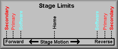
The Image Flat Mirror stage uses a different approach to generating the HOME signal. In this case, there was not enough room to mount a separate optical interrupter for the HOME signal. Instead, the REV limit switch is used for this purpose. That is, what is normally the REV limit switch now provides both the REV limit and the HOME signals. Thus, to 'Home' the stage, it is run in the reverse direction until it contacts the reverse limit switch. The resulting signal both clears the encoder count buffer and tells the controller that the stage has hit the reverse limit. Because the stage is moving the mirror in translation the in and out positions are not very critical and the limit switch hysteresis does not create a problem. The other limits, the forward primary and the secondary forward and reverse, all perform the expected functions. That is, as in the diagram below, they are reached in the usual order: software, primary, and secondary.
Directly below the motor are the primary motion limits. These limits can only be reached if for some reason the software limits fail. If they are reached, either the FLSC, forward limit switch, or the RLSC, reverse limit switch input to the Galil controller is brought to ground and the controller ramps down the motion of the stage. At this point, you can back out of the limits but you can't go in the direction of the limit.
The secondary limits are shown directly to the left of the motor. They are DPDT switches that, if reached, both breaks the current path to the motor and pulls the Galil input bit IN3 low to signal the controller that the limit has been reached. These are the final limits in the system and if the stage moves far enough to trip them the stage must be moved out of the limit by hand. The other section of the secondary limit switches are wired in parallel so they only tell the controller that the stage has hit a limit but not the direction. Direction information can be obtained from the primary limit switches.
The EL-1236 stage interconnect box is wired to pass the position information, limit switch states, and motor power. The power for the motor is wired to two sets of twisted pairs in the stage cable between the Galil amplifier connection panel and the stage interconnect box. The twisted pairs are AWG 22-gauge wire. The two pairs are tied together at terminals 1 and 2, and 3 and 4 of TB1 in the EL-1236 box. From there, AWG 18-gauge wires connect to the motor via pins 1 and 2 of JB2. Also, the secondary limits signal and return are fed through pins 3 and 4 of JB2.
A 10-pin ribbon cable from the servo motor encoder connects directly to a like connector on the EL-2260 encoder buffer board that is mounted inside the interconnect box. (This is the same board is used in DEIMOS and HIRES). Unfortunately, to disconnect this cable the cover has to be removed from the box. The power for this board comes from the logic supply mounted on the Galil controller mounting plate. The +5V and ground lines are routed to the EL-1236 box via pins 11 and 12 of JB1. The output of the encoder buffer board is connected to the terminal strip inside of the interconnect box by a 10-pin flat ribbon cable. As this is a single-loop encoded stage, the motor encoder signals leave the interconnect box via JB1 and connect to the Galil amplifier connector J13.
At the top center of sheet 1 are connections to the logic power supply. These are all wired inside the connector panel from pins on the stage cable connectors to pins on the large connector J10 with black and red wires. These wires come from the long terminal strips on the Galil panel. From there they go to the logic power supply. Next to the logic power supply connections is the connection from the Lambda +28V power supply. This is the power that is supplied to the amplifiers to run the servo motors. On the left side of the drawing is the controller box. The connections shown between the controller and the amplifier are made through flat ribbon cables.
Sheet 2
Simplified Brake Diagram
The Image Flat Mirror stage is one of three stages that use an electro-mechanical shaft brake to lock the stage into position at the end of movement. The brake is applied when the power to it is off. To release the brake, the software tells the Galil controller to set I/O bit 38. This turns on the Opto-22 I/O relay in channel 13 of I/O relay rack #4. This in turn applies 28 volts from the Lambda motor power supply to the brake, releasing it. At this point, the stage can be moved. At the completion of the motion the brake is again applied to lock the stage into position.
Low Dispersion Flat Mirror Stage Wiring, EL-3372, sheets 1 and 2
Sheet 1
Simplified Stage Diagram
The Low Dispersion Flat Mirror stage moves the flat mirror in and out of the light path. The normal operation of this stage is to just move it between two positions: in and out with no intermediary stops. This is accomplished by use of a constrained motion, linear stage.
Sheet 1 of the schematic shows the wiring of the stage. Looking at the schematic, the upper right side of the schematic shows the servo motor and it's encoder. In the middle of the drawing are representations of the EL-1236 Stage Interconnect Box (inside the dashed lines) and the Galil amplifier mounted connector panel. The left side of the drawing shows the the Galil controller and amplifier. The servo motor is a standard Galil 50-1000 motor. It is rated at 10.8 oz-in/A (30 oz-in peak) of torque and it's encoder has 1000 counts in quadrature that the controller decodes to 4000 counts per revolution. This stage uses single-loop encoding so the servo loop is closed around the motor encoder.
The Low Dispersion Flat Mirror stage uses a third approach to generating the HOME signal. In this case, there was not enough room to mount a separate optical interrupter for the HOME signal. The REV and FWD limits are implemented using optical interrupters. Similar to the Image Flat Stage, the REV limit signal is used for 'homing' the stage. That is, what is normally the REV limit signal now provides both the REV limit and the HOME signals. Thus, to 'Home' the stage, it is run in the reverse direction until it senses the reverse limit. The resulting signal both clears the encoder count buffer and tells the controller that the stage has hit the reverse limit. The other limits, the forward primary and the secondary forward and reverse, all perform the expected functions. That is, as in the diagram below, they are reached in the usual order: software, primary, and secondary.
When homing the stage, the software enables the optical interrupter by asserting the FIDUCIAL ENABLE signal at output OUT4. With the fiducial on, the software can then search for the edge of the 'Reverse' flag to zero out the encoder count buffer. The process is actually a little more involved then this and is covered in the Introduction section.
Directly below the motor are the primary motion limits. These limits can only be reached if for some reason the software limits fail. If they are reached, either the FLSD, forward limit switch, or the RLSD, reverse limit switch input to the Galil controller is brought to ground and the controller ramps down the motion of the stage. At this point, you can back out of the limits but you can't go in the direction of the limit.
The other section of the secondary limits are shown directly to the left of the motor. They are DPDT switches that, if reached, both breaks the current path to the motor and pulls the Galil input bit IN4 low to signal the controller that the limit has been reached. These are the final limits in the system and if the stage moves far enough to trip them the stage must be moved out of the limit by hand. The secondary limit switches are wired in parallel so they only tell the controller that the stage has hit a limit but not the direction. Direction information can be obtained from the primary limit switches.
The EL-1236 stage interconnect box is wired to pass the position information, limit switch states, and motor power. The power for the motor is wired to two sets of twisted pairs in the stage cable between the Galil amplifier connection panel and the stage interconnect box. The twisted pairs are AWG 22-gauge wire. The two pairs are tied together at terminals 1 and 2, and 3 and 4 of TB1 in the EL-1236 box. From there, AWG 18-gauge wires connect to the motor via pins 1 and 2 of JB2. Also, the secondary limits signal and return are fed through pins 3 and 4 of JB2.
A 10-pin ribbon cable from the servo motor encoder connects directly to a like connector on the EL-2260 encoder buffer board that is mounted inside the interconnect box. (This is the same board is used in DEIMOS and HIRES). Unfortunately, to disconnect this cable the cover has to be removed from the box. The power for this board comes from the logic supply mounted on the Galil controller mounting plate. The +5V and ground lines are routed to the EL-1236 box via pins 11 and 12 of JB1. The output of the encoder buffer board is connected to the terminal strip inside of the interconnect box by a 10-pin flat ribbon cable. As this is a single-loop encoded stage, the motor encoder signals leave the interconnect box via JB1 and connect to the Galil amplifier connector J14.
At the top center of sheet 1 are connections to the logic power supply. These are all wired inside the connector panel from pins on the stage cable connectors to pins on the large connector J10 with black and red wires. These wires come from the long terminal strips on the Galil panel. From there they go to the logic power supply. Next to the logic power supply connections is the connection from the Lambda +28V power supply. This is the power that is supplied to the amplifiers to run the servo motors. On the left side of the drawing is the controller box. The connections shown between the controller and the amplifier are made through flat ribbon cables.
Sheet 2

Simplified Brake Diagram
The Low Dispersion Flat Mirror stage is one of three stages that use an electro-mechanical shaft brake to lock the stage into position at the end of movement. The brake is applied when the power to it is off. To release the brake, the software tells the Galil controller to set I/O bit 39. This turns on the Opto-22 I/O relay in channel 14 of I/O relay rack #4. This in turn applies 28 volts from the Lambda motor power supply to the brake, releasing it. At this point, the stage can be moved. At the completion of the motion the brake is again applied to lock the stage into position.
CCD Shutter Limit and Solenoid Wiring, EL-3379
Simplified Wiring Diagram
The CCD shutter is a two blade design that alternately moves one blade and then the other into the light path to block off the CCD. The drawing above shows that there are two air pistons and two air solenoids in the system. The box on the left-hand side of the diagram represents the EL-1183 Shutter Controller box. This box receives a level from the CCD controller and generates the correct control signals for the shutter. Refer to the diagram
for a discussion of the open/close cycle. Assume that at first, as in diagram 1, that the shutter is closed and that the left-hand blade is in the beam. The CCD Controller sends a positive level to tell the shutter to open. The left blade moves out of the beam as shown in diagram 2. When the exposure is done, the CCD Controller lowers the signal and the shutter controller move the right-hand blade into the beam as shown in diagram 3. For the next exposure, the CCD Controller again raises the shutter signal but this time the shutter controller moves the right-hand blade out of the beam as in diagram 4. At the end of the exposure the left-hand blade is moved back into the beam and we end up in our starting configuration as in diagrams 1 and 5.
The controller actuates the solenoid by applying 24VDC to the coil. To move the piston in the other direction the controller reverses the polarity to the coil. The power supply for the solenoids is located inside the controller box. The controller uses a programmed gate array to generate the logic. For a more thorough discussion, see the EL-1183 circuit description in the Miscellaneous Drawings section of this manual.
The shutter limits schematic EL-3379 shows the additional junction box that is mounted on the shutter assembly. It contains an input connector, a terminal strip, and two output connectors. The terminal strip serves as a breakout point for the signal and a place to probe the signals coming back from the limit switches. The schematic also shows a terminal strip for the solenoids and a connector for the drive signals. The terminal strip and connector are mounted on the backside of the optical substructure. Also, as noted on the schematic, terminals eight through twelve are used for the hatch solenoid.
Entrance Hatch Stage Wiring, EL-3380
Simplified Wiring Diagram
The entrance hatch schematic shows the wiring for the air piston limits and the air solenoid. As the schematic shows, the hatch is controlled by two of the Galil Controller's expansion I/O bits. Bit 27 is pulsed to open the hatch and bit 28 is pulsed to close the hatch. This translates to channels two and three on Opto-22 relay rack #4 located in locker #3. We use Honeywell #73419AN2NN00M1G011P3 120VAC latching valves. These valves use an 'over center' mechanism that enables us to pulse the relay coil to change the position of the Bimba air cylinder that is used. The obvious advantage here is that once the pulse is sent to the relay it latches in the appropriate position and the coil is left de-energized. Thus, heat is only produced during the 400 microsecond pulse that the controller sends out.
The connections made to the solenoid are shown going through connector PJ20. The solenoid is located at next to the shutter solenoids and uses the same terminal strip, TB-SOL, to make the needed connects.
Below the solenoid on the right-hand side of the schematics are the hatch stage limit switches. These are magnetic reed switch type switches. They are secured to the Bimba air cylinder with a band clamp that allows them to be loosened and moved along the body of the cylinder. These are adjusted by opening or closing the hatch and then moving the switch in one direction until the switch signal drops out. Mark this position and then move the switch in the opposite direction until it drops out. Again, mark this position and then move the switch to the center on the range. The set the hatch to the other position and follow the same procedure for the opposite switch.
Manual Control Paddle. EL-3385
Note: The manual paddle schematic is too large to present here.
Please use your viewer to examine the schematic.
There are two manual paddles provided as aides in maintenance and troubleshooting the instrument. The paddles are hand held units that can be attached to the bottom of the instrument. Once connected, they can be used to move the stages associated with the paddle. Each of the two paddles are color coded and they have different gender connectors to connect them to the system. The paddles themselves are actually built the same but have different label plates. Though they are built the same, some paddles do not have some of the components installed on the face plate. As an example, the paddle for Galil controller #1 has the switches and LED's to operate the hatch stage. The paddle for Galil controller #0 has the switches and LED's but they are tied off inside the body of the paddle and thus not available on the face plate. A spare paddle was shipped with the instrument. It has new face plates for each of the controllers. This will allow a technician to open the paddle body, install or remove the required switches and LED's, and add the appropriate face plate. This also points out that in an emergency, the paddle for controller #1 could be substituted for controller #0 as long as the user keeps straight what functions are available on that controller. The converse is true with the exception of the hatch controls.
The schematic is fairly simple. Each of the switches when activated supplies a ground to the associated input channel of the Galil's expansion I/O. The Auto/Manual switch on the right-hand side of the sheet does two things. First, in the manual position, it grounds out the Auto/Manual bit via pin 7 of the paddle connector. Second, in the manual position, it supplies +5 volts to the LED's. The incoming signals come from one of two places. The software can pull down the inputs for the FWD LIMIT, REV LIMIT, or STAGE MOVING LED's depending on inputs from the various stages. These LED's states depend on the setting of the motor thumbwheel switch. In the case of the HATCH OPEN and HATCH CLOSED Leeds, these inputs are wired directly from the air piston limit switches and give correct indications regardless of the motor switch setting. Note, as shown on the EL-3386 schematic, that they are also wired as inputs to Galil controller #1. The I/O connections are explained in the next section (EL-3386).
Sheet 1
Simplified Wiring Diagram
This schematic shows how the manual paddle is connected to the Galil controller. All signals to or from the paddle are connected to solid-state Opto-22 relays. The diagram above shows the paddle signals and the I/O channel that the Galil reads. Note: if a failure of the paddle is suspected, a quick check of the LED's on the Opto-22 relay rack will tell you if the signal is present. Simply push a pushbutton or change a thumbwheel switch to see it's associated relay indicator LED change state. These signals/LED's can be checked regardless of the state of the Auto/Manual switch. Also, this is true for both the input and output signals. A difference exists between the two wiring diagrams EL-3385 sheets 1 and 2. That is an extra set of controls on the paddle for Galil controller #1. These pushbuttons and LED's are used to open and close the entrance hatch. Because ESI doesn't use any other pneumatic stages these controls are not mounted on the paddles face plate for controller #0.
Sheet 2
Simplified Wiring Diagram
This schematic shows how the manual paddle is connected to the Galil controller. All signals to or from the paddle are connected to solid-state Opto-22 relays. The diagram above shows the paddle signals and the I/O channel that the Galil reads. Note: if a failure of the paddle is suspected, a quick check of the LED's on the Opto-22 relay rack will tell you if the signal is present. Simply push a pushbutton or change a thumbwheel switch to see it's associated relay indicator LED change state. These signals/LED's can be checked regardless of the state of the Auto/Manual switch. Also, this is true for both the input and output signals. A difference exists between the two wiring diagrams EL-3385 sheets 1 and 2. That is an extra set of controls on the paddle for Galil controller #1. These pushbuttons and LED's are used to open and close the entrance hatch. Because ESI doesn't use any other pneumatic stages these controls are not mounted on the paddles face plate for controller #0.
![]()
![]()
![]()