Slitmask Alignment Procedure
Working Draft! See also the new Cookbook
Overview
The procedure described here is based on that developed for LRIS slitmasks
by the DEEP group at UCSC.
It uses alignment boxes and alignment objects (stars)
to position the mask against the sky, by centering the stars within the boxes.
This approach has the following advantages:
- Alignment stars are chosen to be fairly bright, so that relatively
short exposure times (of order 30s) are sufficient to obtain accurate
positions;
- The mask remains installed throughout the procedure - no overhead in
moving the slitmask and no repeatibility worries;
- Only a small area of the detector is involved, so we may employ subraster
read-out of the CCDs to speed the process.
Using the procedure described here, we have performed successful alignments of
LRIS in under 20 minutes,
from the end of one science integration to the start of the next. LRIS
requires close to 10 minutes for two grating-mirror changes and a mask-to-mask
change.
Steps in the Alignment Procedure
NOTE: the following has been largely supplanted to use the new xbox
task -- see the Cookbook.
Suitable alignment objects are selected during mask design and
corresponding alignment boxes (typically 4 arcsec square) are cut during mask
fabrication.
Afternoon Preparation
In the afternoon, take a direct image of the dome (or internal lamp) through
each mask, and note the locations of all the alignment boxes. These need
to be accurate to +/- 2 or 3 pixels. Put these coordinates into a text
file for each mask (format x,y,ID; one line per box), eg:
# box centers for Mask A:
1121.  1718.   Align_star_1
1308.  1672.   Align_star_2
 996.   312.   Align_star_3
Use implot to measure the width of the boxes and epar qbox.
(After I have the text files and box widths, I like to run "qbox"
on each image (letting it find whatever position for the star) to verify
the box locations. Type "I" anytime to interrupt.)
Alignment
In the script below, I have assumed science integrations
are being taken in single-amp mode; two-amp readout is faster and is
preferred for alignment.
To set up on a mask at the telescope:
- Slew to position and set correct PA. Place the instrument
in direct imaging mode; change to two-amp read-out.
- Take an image of the field. Identify an alignment star and use "mshift"
to calculate the needed offset to the alignment box location. Insert the mask,
and start guiding on the guide star.
- Take a direct image through the mask -- stars should be visible in the
boxes.
- Use "qbox" to find all the star/box positions and produce the solution.
Communicate the incremental offsets to the OA, or apply them yourself
if you've printed out the DCS commands.
- Repeat the last 2 steps as needed until the alignment stars are centered
in their boxes.
- Move the grating into place. Change back to one-amp
read-out and begin science integration.
qbox
The script task qbox calls the two spp tasks
mboxfind and maskalign. The calling
sequence is simple:
qbox lris0054 maskA.box

... where lris0054 is the IRAF image taken through the slitmask,
and maskA.box is the text file with the box centers.
The centering algorithm is based on edge detections for both the
stellar image and the alignment boxes. The only required inputs are star
FWHM and box size in pixels. For each star/box
pair, a plot shows both x- and y-profiles through the box; the user sets
a single sky level and the algorithm finds both the box and star centers.
Generally only two keystrokes are needed for each alignment star/box.
After all the alignment stars are examined, the solution is shown graphically
and the user must simply use a single keystroke to exit. The entire
alignment solution takes well under 1 minute to execute once the image is
available for analysis.
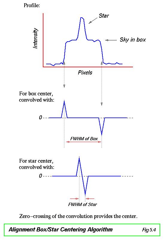
With a priori knowledge of the size of the alignment boxes and
approximate FWHM of the alignment stars,
a very robust centering algorithm is available
(similar to that used in the IRAF "identify" task). The profile is convolved
with the profiles shown below and
the zero-crossing indicates the center. This method weights toward the
edges of the features (stars or box) provided the FHWM is appropriate. It is
insensitive to errors in background level and the presence
of most cosmic rays.
Pickoff Mirror Guide Star TV Coords
If you know the x,y coord (in arcsec) of the pickoff mirror star, you can
predict the position in TV pixels on the slit-viewing camera. The formulae
below assume 2x2 binning (ie 0.5" pixels) on the TV camera.
TVx =  85 - sim(y) / 0.5   (sim(y) is negative on mirror 2)
TVy = 204 - sim(x) / 0.5
NB -- these numbers have been derived from real data but not yet tested.
Nicole Vogt at UCSC is developing a more accurate calibration of these numbers,
and observers using her mapping have reported excellent results.
Andrew C. Phillips / Lick Observatory
Last modified: 06 jun 97
phillips@ucolick.org