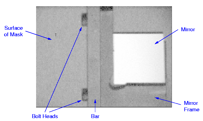
Here's the famous pick-off mirror as seen by the LRIS slit-viewing camera:
pr> fabmask gen_igi mapmask qmask_plot simulator
Currently, you must hand-edit the priorities of the guide star (-1) and the alignment stars (-2).
[This following is very old:]
Here are MY parameter files; some of the parameters are not too obvious,
unless you're familiar with the procedure:
# simulator:
objfile = "2a.test" file of primary objects (NORRIS w/: )
(ra0 = 14.2953) Initial RA of field (can be in hh:mm:ss.ss)
(dec0 = 52.48) Initial Dec of field
(other_obj = "") file of other objects (NORRIS w/: )
(output = "") output list (AUTOSLIT input)
(ha = ) Initial Hour Angle
(exposure = 1.) Total Exposure (hours)
(min_slit = 12.) Minimum slit length (arcsec)
(slit = 1.1) Width of slit (arcsec)
(blue = 7500.) Shortest wavelength of interest
(red = 9000.) Longest wavelength of interest
(dispersion = 1.28) Dispersion in A/pix
(x1 = 1.) Min. X (mm) for mask punch
(x2 = 185.) Max. X (mm) for mask punch
(y1 = 1.) Min. Y (mm) for mask punch
(y2 = 335.) Max. Y (mm) for mask punch
(long_slit_mo = no) Long slit (vs. slit mask) mode
(coord = "") graphics cursor input
PA = [PA of mask]
width = [width of field in arcsec]
where input files (objfile,other_obj) look like this
(ID priority mag RA DEC PA min_bot min_top):
CENTER 9999 1950. 14:17:41.10 52:27:45.00
06:3:36:58:23.5 500 23.53 14:17:53.91 52:30:23.03 INDEF 10.0 10.0
08:4:31:11:22.4 500 22.43 14:17:38.85 52:27:20.80
10:4:40:24:23.L 500 23.07 14:17:27.00 52:24:50.93 25. 14. 18.
REFER_OBJ -2 10.00 14:17:41.10 52:27:45.00
(Note that the "CENTER" line is optional here.)
-----------------------------------------------------------
# mapmask:
objfile = "try1" file of objects
output = "mask.out" output file
ha0 = 0. Hour Angle
(lambda_cen = 7500.) wavelength for refraction
(temp = 0.) Air temp (C)
(pressure = 615.) Air pressure (mm Hg)
(lower_min = 5.5) Minimum length below object (arcsec)
(upper_min = 5.5) Minimum length above object (arcsec)
(box_sz = 4.) Alignment box size (arcsec)
(prescan = 42.) Columns of CCD prescan
(verbose = ) slit review option (y/n)
(mode = "ql")
where input looks like this:
CENTER 9999 1950.0 0:14:42.32 15:29:06.8 53.0
4170 1500 23.00 0:14:29.20 15:28:01.77 40.0 7.5 7.5
4649 1500 23.70 0:14:38.04 15:28:54.59 45.0 7.5 7.5
4939 1500 21.80 0:14:42.80 15:29:23.61 57.9 7.5 7.5
...
B1781 1000 22.40 0:14:49.906 15:32:20.98
B0651 1000 21.60 0:14:41.701 15:29:07.13
4337 1000 23.43 0:14:26.345 15:28:21.10
GS -1 20. 0:14:38.34 15:29:42.69
4910-AS -2 19.13 0:14:33.311 15:29:21.35
6794-AS -2 19.55 0:14:49.304 15:32:16.14
6208-AS -2 20.14 0:14:52.585 15:31:21.29
(Note the mirror and mask-alignment stars have specific priorities.)
-----------------------------------------------------------
# fabmask:
input = "mask.out" input file
output = "fab.out" output file
(format = ) output format (lick|keck)
(tool_diam = 0.8) tool diameter (mm)
(punch_width = 0.5) punch width (mm)
(double = no) double punch?
(x_zpt = 0.) X zeropoint offset (normally 0)
(y_zpt = 0.) Y zeropoint offset (normally 0)
(mode = "ql")
where input file looks like this:
###########
##
## MAPMASK: INPUT = try1
...
##
## Xobj Yobj Ymin Ymax Rel_PA CCDx CCDy Code Mag ID
##
124.724 9.544 15.291 3.500 2.50 1172.9 2105.9 1500 23.20 6376
172.458 19.506 21.657 15.291 0.00 1475.6 2041.6 1000 22.40 B1781
120.661 23.108 24.558 21.657 0.00 1147.1 2018.4 -2 20.14 6208-AS
173.516 26.661 28.111 25.210 0.00 1482.3 1995.4 -2 19.55 6794-AS
124.826 39.581 47.660 31.344 8.00 1173.5 1912.0 1500 21.60 6107
86.788 53.584 56.116 47.660 0.00 932.3 1821.7 1000 22.40 B1043
...
122.994 314.309 317.946 310.932 0.00 1161.9 139.1 1000 23.06 B0099
182.155 321.582 332.000 317.946 0.00 1537.1 92.2 1000 23.43 4337
154.149 185.479 185.579 185.379 0.00 1359.5 970.5 -1 20.00 GS
==============================================================================
Yet more info -- the cookbook approach (based in part on the Aug 95 run):
I. Edit and Run cl < sim1.cl
where sim1.cl looks like this
# Mask 1 0:14:42.32 15:29:06.8
simulator.ra0=0:14:42.32
simulator.dec=15:29:06.8
simulator.red=8000.
simulator.blue=7000.
simulator.PA=53.
simulator.ha=0.
del tmp1,tmp2,tmp3,try1
sim mask1.sim oth="" # Demonstration; verify center
sim mask1.sim oth=cat/bnoz.sam out=tmp1 # Select primary, next priority
sim tmp1 oth=cat/i.sam out=tmp2 # Select primary, next priority
sim tmp2 oth=cat/f.sam out=tmp3 # Select primary, next priority
sim tmp3 oth=cat/b.sam out=try1 # Select primary, lowest prior
# Note that the input file, mask1.sim, has slit lengths and PAs added as needed.
# This script is used to select targets from different priority catalogs -- the
highest priority objects belong to "mask1.sim", the next are in "cat/bnoz.sam",
etc, until the lowest priority, "cat/b.sam". Each time simulator is run,
the first thing you do is select all of the primary targets -- that's
to say, you want to KEEP all the primary targets, and fill in additional
targets from the secondary list. In this way you can build up the mask
from highest--to-lowest priority objects. For simpler cases (all objects
are from the same general catalog) you can just run simulator once, rather than
creating a cl-script for multiple passes. Note that each catalog can have its
own set of internal priorities. The automated select function in simulator
will use these priorities while selecting objects, attempting to maximize the
sum of priorities appearing on the mask.
(Note added 07 may: There's now a "remain" parameter in simulator,
which, when given a file name, will produce a list of target objects
which were _not_ used. This is useful for designing several masks
which cover the same area of the sky.)
Ia. Edit the output ("try1") to update priority levels -- alignment stars (-2),
pickoff mirror guide star (-1)
II. Run mapmask try1 map.out verb+ > map.review
or
mapmask try1 map.out verb+ | page
IIa. (opt) Edit output (map.out) to adjust any slit ends as desired.
IIb. (opt) Run qmask_plot to get plots of the mask as designed.
III. Run fabmask map.out mask.ascii form=lick tool_diam=0.43
# The value of "tool_diam" depends on the slit-width desired.
IV. Write the file(s) to diskette:
!fdformat -db LRISMASK
!/home/taiyang/wirth/bin/mwrite -t mask1.asc a:
!/home/taiyang/wirth/bin/mdir
!eject
V. Relax, you're done.
=============================================================================
SOME MISCELLANEOUS NOTES:
Your guide star should be something suitable for guiding on (see the LRIS
documentation; we've been quite successful with objects around 19-20 mag in
R).
Alignment stars should be in the range of 19-21 R magnitude, for alignment
exposures of 30--60 sec. Remember, for the alignment box method you want
both good _stellar_and_sky_ signal. Outside of the stated magnitude range,
there's a poor balance between sky and star. Fainter stars require longer
exposures, brighter can saturate. It's better if the alignment stars are all
of similar magnitude as well.
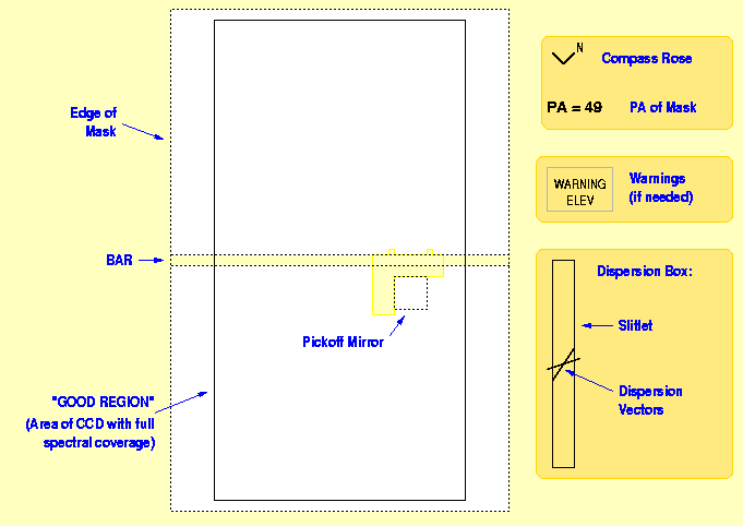
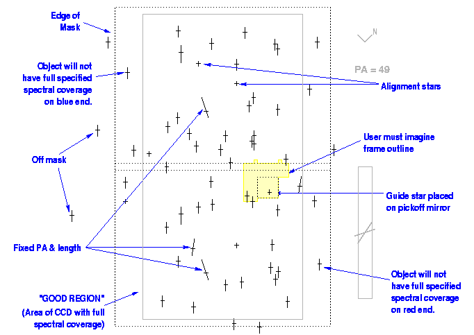
SIMULATOR shows the outline of the pickoff mirror, but in addition there
is a frame to the mirror which is _not_ shown. This frame projects 12 mm
from the edge of the mirror toward the center of the mask -- thus, you should
avoid selecting objects that are within about 15" of the left edge of the
mirror. Simlarly, the mirror frame extends a fair distance along the
bar on either side of the mirror:
** **
BBBBBBBBBBBBBBBBBBBBBBBBBBBBBBBBBBBBBBBBBBBB
BBBBBBBBBBBBBBBBBBBBBBBBBBBBBBBBBBBBBBBBBBBB
|||||||||||||||||||||||||||||||||
|||||||||||||||||||||||||||||||||
|||||||mmmmmmmmmmmmmm
|||||||mmmmmmmmmmmmmm
|||||||mmmmmmmmmmmmmm
|||||||mmmmmmmmmmmmmm
|||||||mmmmmmmmmmmmmm
|||||||mmmmmmmmmmmmmm
|||||||mmmmmmmmmmmmmm
where B=bar, m=mirror, |=frame; the extension is where the mirror is
bolted to the bar (**=screw head).