PANE example: PHDU from HIRES Mosaic
The first few cards are the mandatory keywords as inserted
by the CFITSIO library.
SIMPLE  =                    T / file does conform to FITS standard
BITPIX  =                   16 / number of bits per data pixel
NAXIS   =                    0 / number of data axes
EXTEND  =                    T / FITS dataset may contain extensions
COMMENT   FITS (Flexible Image Transport System) format is defined in 'Astronomy
COMMENT   and Astrophysics', volume 376, page 359; bibcode: 2001A&A...376..359H
Note above that BITPIX=16, which indicates that the FITS file contains
big-endian signed 16-bit two's complement integers (range -32768 to +32767).
It is the case for all of the UCO/Lick CCD hardware that the
analog-to-digital conversion produces unsigned 16-bit integers
(range 0 to 65535).
The structure of two's complement arithmetic allows these data values
to be written into a FITS file simply by flipping the high order
(sign) bit and setting the next two FITS keywords to these values.
BZERO   =                32768 / offset data range to that of unsigned short
BSCALE  =                    1 / default scaling factor
This is the date that CFITSIO obtained by querying the system clock
for the POSIX time_t value.
It is the time at which the lickserv2 process
requested the creation of this HDU as part of the skeletal MEF file
into which the pixel stream was descrambled.
It does not directly indicate anything about the time of the exposure
or the time of the movements of the camera shutter.
DATE = '2004-05-20T22:22:47' / file creation date (YYYY-MM-DDThh:mm:ss UT)
In the mosaic data acquisition system created for Keck by UCO/Lick
the multi-extension FITS file is constructed by the lickserv2
process as it captures the incoming pixel stream from the CCD crate.
At that point the only FITS keywords are the ones which describe the
pixel structure of each of the HDUs, but there is a large amount
of extra room in the PHDU consisting of blank FITS card images.
After the pixel stream is captured the FITS file is handed to the
write_image process, and it inserts the following comment
record
to make it clear that write_image is responsible for
the subsequent sequence of FITS header records.
COMMENT BEGIN observation-specific keywords written by write_image
Starting with the initiation of an exposure and proceeding until the
exposure is complete the watch_ccd process has been gathering
various KTL keywords and storing them.
Most of the KTL keywords that watch_ccd gathers are specified in
lists read from a file conventionally named header_info.
When write_image gets the FITS file it queries watch_ccd
for the KTL keywords that apply to this exposure, and then it inserts
sequentially into FITS keywords in the PHDU.
For the overall description of the keywords relevant to various
detectors built by UCO/Lick Observatory see the sections of links
regarding "bundles" of keywords on
this page.
In particular, see
the generated bundle of keywords generated by lickserv/write_image/watch_ccd.
COMMENT BEGIN keywords that came from KTL via watch_ccd
For the keywords that are particular to the HIRES mosaic see
this generated bundle of keywords.
AUTOSHUT=                    F
ERASECNT=                    1
ANTIBLM = 'off     '
ABFREQ  =                   20
NSUBINT =                    0
ROWSHFT =                    0
INSTRUME= '        '
DETECTOR= '        '
At a temperature of 14 Celsius it is plainly evident this was an
engineering exposure.
TEMPDET =          14.61323547
UTB30VEN= 'enabled '
UTB15VEN= 'enabled '
For the HIRES mosaic a new feature was introduced to
give fine control over the exposures of the CCDs.
The ERAMODE keyword indicates which of the CCDs are to be
erased at the start of a (sub)exposure, and the MOSMODE
keyword indicates which of the CCDs are read at the end of a
(sub)exposure.
(The VIDINBEG and VIDINEND keywords document this
more finely by acting as a bitmask indicating which video inputs, i.e.
amplifiers, participate in erase and readout.)
Usually all CCDs will be erased and read, but if it were
desired it is possible to close the shutter, read out some
of the CCDs, erase some of the CCDs, and re-open the shutter.
This allows different amounts of exposure on different CCDs in the
HIRES mosaic by selecting which ones are erased and which ones are
read out.
This feature might be quite valuable if there is an object whose flux
produces a tendency to have double the amount of counts on the "red"
CCD as it does on the "blue" one, or vice versa.
The tricky part of using this is that each shutter closing produces a
multi-extension FITS file containing only the pixels from the
amplifiers which were read, and the exposure time keyword in that
image indicates the most recent (sub)exposure, not the total exposure
which is applicable to the data from amplifiers which were not erased
at the beginning of the most recent (sub)exposure.
ERAMODE = 'B, G, R '
VIDINBEG=                   63
ERASLINE=                    F
FRAMENO =                    0
KEEPPREP= 'true    '
CCDGAIN = 'low     '
CCDSPEED= 'fast    '
CCDPSIZE= '1,1,2048,4096'
NVIDINP =                    6
AMPLIST = '3,3,0,0 '
AMPMODE = 'DUAL:A+B'
MOSMODE = 'B, G, R '
VIDINEND=                   63
In the earliest interfaces for reading out CCDs the parameters that
described the windowing were expressed in binned pixels. This meant
that it was necessary to re-define the readout window any time that
the binning was changed. This interface became even more confusing
with the advent of CCDs having more than one amplifier.
The mosaic of CCDs in DEIMOS prompted a new way of describing
the pixels in the focal plane -- the PANExxxx keywords.
The PANExxxx keywords employ a single coordinate system which is
unique, valid everywhere on the mosaic, expressed in unbinned pixels,
and unconcerned with the constraints of the physical boundaries
between different CCDs and amplifiers.
Furthermore, we allowed for as many as 16 different PANEs, thus
allowing the specification of that many different regions of
interest during a CCD mosaic readout.
The PANExxxx keywords were initially created for the DEIMOS mosaic,
but their operation was not fully implemented until the HIRES mosaic.
Recall that this PHDU is extracted from
this multi-extension FITS file
obtained during engineering checkout of the HIRES mosaic.
As seen in the PANELIST keyword, this image used all 16 PANEs.
(Really there are 17, for the default PANE keyword --
effectively PANE0 -- remains defined as all pixels in the mosaic,
and is not used in this readout.)
The PANEn keywords below correspond to the diagram
below
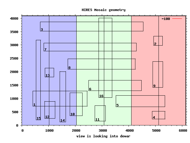
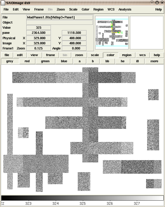
This was a dual-amplifier readout of HIRES, and a careful count of the
number of different PANE+amplifier regions in the above picture gives 41.
The view of the resulting MEF file, with its 41 different FITS IMAGE
extensions, as seen in ds9 is below
The idea of the PANEn keywords was to allow the definition
of multiple, different kinds of regions of interest.
E.g., for DEIMOS spectral exposures some PANEs might be defined to
indicate spectral regions of interest, and/or slitlets of interest.
For DEIMOS direct images other PANEs might be re-defined to match
the alignment holes on upcoming slitmasks.
While leaving the PANEn keywords unchanged, the PANELIST
keyword could then be redefined suitably for the regions of
interest on each different exposure.
One supposed advatage of PANEs was to reduce the amount of disk space
needed to store images, but the explosion in size of disk storage
media since the deployment of these instruments at Keck makes that
moot. Furthermore, the advent of archives means that the regions
not of interest to the initial observer may still contain serendipitous
discoveries to be found during later data mining.
Nevertheless, depending on the CCD controller, the use of PANEs
may reduce the amount of pixels in the readout and data
transfer. For instruments which have that capability this may be
advantageous in reducing the readout time for the mosaic.
PANEFITS= 'normal  '
PANELIST= '1,2,3,4,5,6,7,8,9,10,11,12,13,14,15,16'
PANERROR= 'NO_ERROR'
PANE    = '0,0,6144,4096'
PANE1   = '408,711,2040,568'
PANE2   = '4936,2983,328,344'
PANE3   = '688,3519,3856,344'
PANE4   = '4872,231,488,288'
PANE5   = '3520,687,1832,424'
PANE6   = '2504,1295,1968,384'
PANE7   = '824,2775,3464,296'
PANE8   = '1720,2087,2528,392'
PANE9   = '4904,1415,376,968'
PANE10  = '1800,359,464,856'
PANE11  = '2736,151,392,584'
PANE12  = '856,255,384,640'
PANE13  = '864,1799,336,336'
PANE14  = '1424,119,216,1888'
PANE15  = '528,199,176,2984'
PANE16  = '2880,1039,496,2968'
The following keywords indicate where the FITS file was written
and what its base name was. We encourage users to review the
generated lists of CCD keywords for
DEIMOS and
HIRES
with special attention to the DISKLIST keyword which allows specification
of a colon-separated list of pathnames which will be tried in sequence if there is
some failure writing an image to the path given by OUTDIR. Also see
the DISKFREE, DISKFREP, and DISKIMGS keywords to see
how much disk space is left.
OUTDIR  = '/local/u/kics/data/2004may19'
OUTFILE = 'foobar  '
OVRFLUSH=                    0
PREFLUSH=                  300
The UCO/Lick detectors have numerous keywords related to the
duration of the exposure and shutter operation.
When precise values are desired for the reduction of data
involving dark current and exposure time it is imperative
to review the definitions of
this generated bundle of keywords.
TTIME   =                   24
ELAPTIME=                   24
EXPTIME =           0.00000000
DARKTIME=          24.11120033
SHBLOPTM=           0.00000000
SHBLCLTM=           0.00000000
SHLATOPN=           0.00000000
SHLATCLO=           0.00000000
SHOPNCNT=                    0
SHCLOCNT=                    0
As noted above, internally the data values for each pixel were
unsigned 16-bit integers. That means the data value must never
fall below zero. The CCD controller allows a "video offset" (a data value)
to be applied in order to ensure that variations in voltages and noise
during readout never produce a negative number. There is one video
offset value for every amplifier in use during the readout.
What is most relevant here is to discuss the meaning of the index
value on each of these offsets. The index here represents the
"video input" on the CCD controller, not any particular amplifier.
There is one video input for each amplifier in use,
but their numbering need not be identical nor constant.
For the CCD hardware in most instruments it is possible to permute the
coaxial cables which run between the pre-amps on the dewar and the
video inputs on the CCD controller.
(Indeed, during engineering and debugging it is commonplace to swap
cables to verify which parts of the signal pathways may not be working.)
For a diagram of this wiring with the HIRES mosaic see
this image (or as
PDF). Note that the HIRES diagram
indicates video inputs numbered 1 thru 12 (with only
the odd one in use). For the moment take this as an apology that
despite the best efforts to allow for a complete description of
the real world in software, sometimes engineering diagrams and
code still do not use a self-consistent vocabulary.
The CCD crate which constructs the pixel stream cannot know anything
about permutations of cable connections at the CCD controller.
The information on the cable connectivity is stored as part of the
data available to the lickserv2 process.
When it creates the skeletal FITS file the lickserv2 process
places its notion of the current wiring configuration into each of the
individual IMAGE HDUs.
It is, therefore, incumbent on the engineers to ensure that the
configuration used by lickserv2 gets changed whenever
the cables are permuted.
If not, then the resulting documentary and WCS keywords will be
misleading.
This will probably, but not necessarily, be immediately obvious when
ds9 displays the mosaic image with mismatched alignment.
VIDOFF1 =                 2000
VIDOFF2 =                 2000
VIDOFF3 =                 2000
VIDOFF4 =                 2000
VIDOFF5 =                 2000
VIDOFF6 =                 2000
The CCD subsystem includes a number of string-valued KTL keywords
which are traditionally stored in the infoman or
infopatcher processes.
The GUI for the HIRES mosaic sets the value of the OBSTYPE
keyword, uses it to streamline various configurations of the CCD
subsystem, and uses it to cross-check whether other aspects of
the exposure are consistent with particular kinds of observation.
The SYNOPSIS keyword is generated on-the-fly in the
write_image process by substituting keyword values
specified by the SYNOPFMT keyword.
OBSERVER= 'Clarke  '
OBJECT  = '        '
OBSTYPE = 'unknown '
SYNOPSIS= 'B, G, R 24 s, unknown pane 1,2,3,4,5,6,7,8,9,10,11,12,13,14,15,16'
SYNOPFMT= '$MOSMODE$ $TTIME$ s, $OBSTYPE$ pane $PANELIST$'
Note that we are still in the section of KTL keywords obtained from
watch_ccd by write_image.
In the Keck CCD subsystems it was traditional for some of the
parameters which describe and/or control the structural aspects of the
images to be accessible via KTL keywords.
As seen farther below, it was also traditional for the Keck CCD
subsystems to include records indicating the values of the structural
parameters which were transmitted along with the pixel stream.
This provides the possibility that there can be two separate instances
of FITS keywords detailing such structural parameters, even though
that was never a good idea for a FITS HDU.
The following records have the values of the KTL keywords, not the
structural parameters sent along with the pixel stream.
POSTLINE=                    0
POSTPIX =                   80
PRELINE =                    0
PRECOL  =                   12
None of the designs for the CCD systems in the optical
instruments at Keck included any specifications for an
ability to obtain a precise time stamp of observation
begin or end. As a result, all such timing information
is obtained via interactions between various subsystems.
In actual use on the telescope the list of KTL keywords gathered by
watch_ccd conventionally includes a timestamp
which is obtained from the Keck DCS via the KTL keyword named
UTC.
The CCD crates at Keck conventionally broadcast messages that
indicate the opening and closing of the shutter, and the
transit times for these messages is usually quite small.
In typical use the list of keywords for the watch_ccd process
indicates that the DCS UTC keyword should be obtained
as part of the keywords gathered in response to the message indicating
the beginning of the observation.
Unfortunately, there is no mechanism for guaranteeing how the
value of the DCS UTC keyword is related to the timing
of the operation of the instrument shutter.
As the watch_ccd process receives the exposure sequence
broadcasts (i.e., erase, shutter open, shutter close) from the CCD
crate it runs through its corresponding list of KTL keywords
to be collected.
For each keyword watch_ccd issues a KTL read to
the appropriate subsystem and then awaits the response from
that subsystem.
The response time depends on the load of the system being queried, and
it is possible that a subsystem will not answer within a timeout of
many seconds, thus delaying the query for the subsequent keywords by
that much time.
In order to provide a cross-check on the exposure time keyword
obtained from Keck DCS, watch_ccd collects the POSIX
time_t values when it receives the broadcast messages
about the first shutter opening event after the CCD is erased,
and the final shutter closing event before the CCD readout.
These values can, of course, only be as accurate as the Unix
system clock, and they do not include sub-second information.
Many steps have been taken in the design of watch_ccd
and the crafting of the lists of keywords for it to collect
in order to reduce the likelihood of trouble when collecting
any keywords, including the time stamps.
Nevertheless, under adverse circumstances we have seen the value of
the DCS UTC keyword differ from the DATE_BEG keyword
by as much as 30 seconds. Observers who need precise times for
the observations should compare the various time stamps
and use whatever seems to make the most sense.
Note that these keywords differ from other FITS DATExxxx keywords
because they are connected with underscore rather than hyphen.
This choice was made in anticipation of a FITS WCS paper V,
in which it is supposed that the FITS standard will designate
new "reserved" keywords with hyphens which may have similar,
but perhaps not identical, meanings.
DATE_BEG= '2004-05-20T22:22:20'
DATE_END= '2004-05-20T22:22:44'
COMMENT END   keywords that came from KTL via watch_ccd
As part of any sending any pixel stream to lickserv2
the CCD crates always include the metadata which describe the
structural properties of the image.
This is necessary so that even in the absence of any of the KTL
keywords (from the various subsystems of the Keck telescope and
instrument) it is still possible to descramble the image and insert it
into the FITS file.
The metadata are contained in a structure called imparm.
The lickserv2 process hands this structure to
write_image along with the skeletal FITS file, and
the following keywords are generated and inserted from
the data in that structure.
As noted above, some of these structural parameters
have meanings similar, or identical to, KTL keywords used
to control or document the CCD readout.
Since the time of the original Keck CCD systems these structural
parameters have traditionally been written into the FITS header
with keywords that have the same names as the KTL keywords.
It has always been poor form for a FITS HDU to have more than
one instance of a FITS keyword with a value.
In some cases the values of the keywords duplicated in Keck HDUs
have had different values, or even different data types.
This ambiguity was the inspiration for, as a minimal remedy,
enhancing the write_image code to add the COMMENT records.
At least to a human these will hopefully indicate the origin of
the two different instances and permit the possibility of making
a rational choice about which value is relevant.
In the original single-HDU FITS files produced by the Keck CCD
systems these keywords were the only means of identifying which
regions of pixels in the image were prescan and overscan, particularly
in the case of the CCDs which were read using more than one amplifier.
The conventions for using those keywords were, however, not well
documented and completely peculiar to Keck instruments.
With the advent of MEF files, where the pixel stream from each
amplifier goes to one (or more) separate IMAGE HDUs, the
lickserv2 process ensures that each HDU contains both the WCS
keywords and the NOAO/IRAF image section keywords.
These keywords provide unambiguous and community-standard ways
of identifying which pixel regions are which.
It may be possible that subsequent CCD instruments will omit
the old and duplicate keywords.
COMMENT BEGIN keywords that came from CCD crate imparm structure
IMTYPE  = 'MOSAIC  '
PRECOL  =                   12
PREROW  =                    4
PRELINE =                    0
POSTLINE=                    0
ERASLINE=                    0
KEEPPREP=                    1
PREFLUSH=                  300
OVRFLUSH=                    0
DETCNFID=                 1002
VIDINACT=                   63
BINNING = '1,1     '
CCDSUM  = '1 1     '
AMPPSIZE= '[1:1024,1:4096]'
DETLSIZE= '[1:6144,1:4096]'
COMMENT END   keywords that came from CCD crate imparm structure
COMMENT END   observation-specific keywords written by write_image
The last thing that write_image does before flushing
the FITS file to disk is to ask CFITSIO to perform the FITS checksum
operation on each of the HDUs. In the case of the PHDU it is possible
to compare the value of the DATE keyword with the comment of the
checksum keywords and see how much time elapsed between the
creation of the skeletal FITS file by lickserv2 and the
completion of keyword insertion by write_image.
CHECKSUM= '9VUAAVT39VT9AVT9'   / HDU checksum updated 2004-05-20T22:23:22
DATASUM = '         0'         / data unit checksum updated 2004-05-20T22:23:22
END
Steve Allen <sla@ucolick.org>
Initial deployment 2000-11-16T22:33:19
$Date: 2010/04/16 21:15:03 $