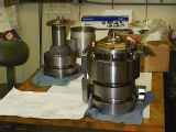
Photo by Barry Alcott (UCO/Lick)
|
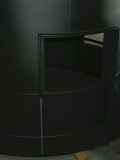
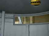
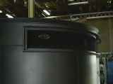
| Side view of a mockup DEIMOS model Photo by Barry Alcott (UCO/Lick) |
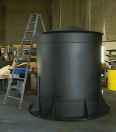
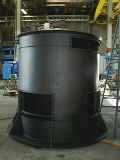
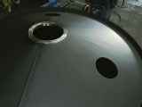
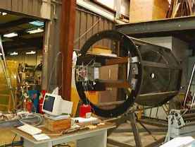
| Frame and outer shell constructed at L&F Industries, Huntington Park, Calif. Photos by Eric James (UCO/Lick) |
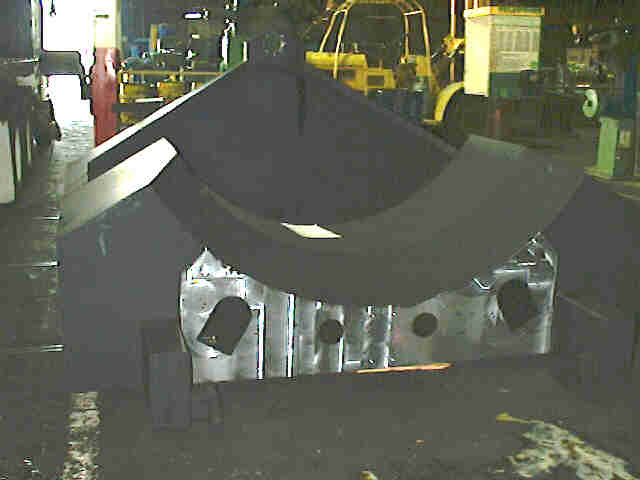

| The shell which will contain all of the DEIMOS components will rotate within and be supported by this cradle structure. Photos by Eric James (UCO/Lick) |
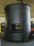
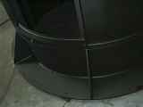
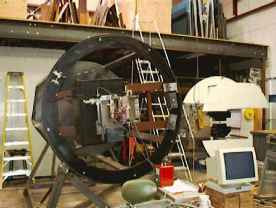
| The whole DEIMOS spectrograph will rotate to counteract the field rotation that is a result of tracking with an Alt-Az mounting. Here are the wheels that will carry the load. |
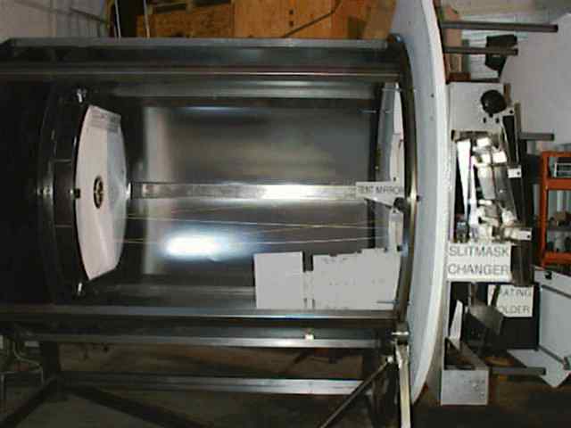
| Test fixture is used in the UCO/Lick Observatory Instrument Lab to check components as they are assembled. |
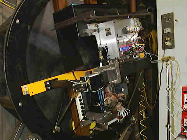
| Test fixture has been shortened and located against a wall to allow space for incoming components. |
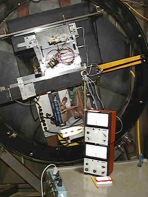
| MAR gauges capable of measuring displacements on the order of microns are used to determine flexure of the grating handler at various spacial orientations. |
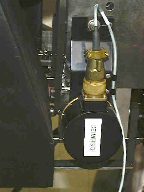
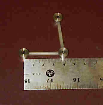
| To the left of the encoder (labeled DEIMOS 3) one can see the tooling balls that are used to precisely locate the grating stage. |
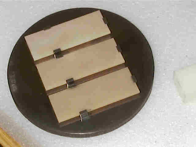
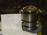
| These are three of the backing plates made of Aluminum
Nitride that will hold the
CCD chips in the mosaic at the focal plane. The Invar plate that they are mounted on
is 5" diameter. Photo by Dave Cowley (UCO/Lick) |
|
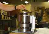
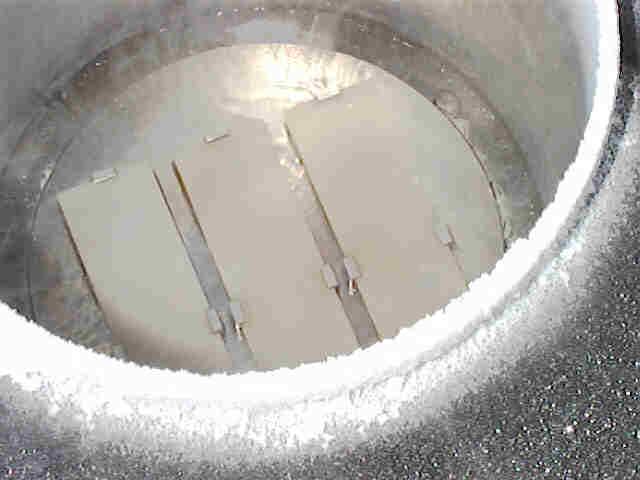
The Aluminum Nitride and Invar assembly is put into liquid Nitrogen to
check the thermal stability of the components at typical operating
temperatures. Photo by Dave Cowley (UCO/Lick) |
| This is a photo of a component of the CCD mounting fixture. The Aluminum pieces are held by rods made of G-10 (a form of glass epoxy) that will allow deflection in the focus direction. |
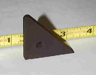
| This carbon fiber piece is being considered as part of a backplane for the CCD mosaic. |
This page is maintained by Jim Burrous
 Jim@Lick.UCOLick.org