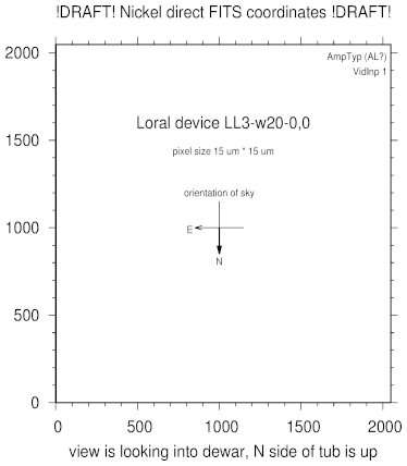
Nickel Direct coordinates
coordinates for Dewar 2 as used for Nickel Direct
as a PDF file
This CCD was fabricated as part of a collaboration between the
Lick CCD lab and Loral.
The subseqent image link from Wei Ming Zhi documents the
Lick3 CCD pinout and silicon layout.
The pinout image shows the CCD viewed as front-illuminated.
The CCD in dewar 2 is thinned and back-illuminated, thus as viewed
looking into dewar 2 the pinout image is flipped left-to-right.
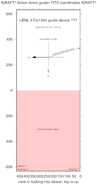
coordinates for the guider on the Nickel Spectrograph
as a PDF file
The field of view of the guide CCD in direct mode would be about 7
arcmin (N/S) x 10 arcmin (E/W) but that is heavily vignetted.
These diagrams are a synthesis of the contents of what should be
several separate diagrams and documents.
The engineering diagram documenting the Nickel direct focal plane
should not include
-
the device name of the CCD
-
the designations of the video inputs
-
the designations of the amplifier types
-
the PANE coordinates
This is a draft. It all deserves double checking.
Please let me know if anything seems awry.
The FITS coordinates can be redefined, but the current
coordinates indicate the manner in which the ucam
code writes the pixels into the FITS image array.
Steve Allen <sla@ucolick.org>
Initial deployment 2011-03-14T18:00
$Id: nickel_direct.html,v 1.9 2019/12/18 18:05:58 sla Exp $