ShaneAO: Summary of predicted sensitivity figures for the ShARCS camera on the Shane 3-m telescope at Lick Observatory
The Lick Observatory’s Shane 3-meter telescope is receiving a new infrared camera, adaptive optics system and laser guide star, collectively called ShaneAO. We present the results of modelling the emissivity and throughput of the ShaneAO system in the form of sky backgrounds and limiting magnitudes in the J , H and K bands for point sources and constant surface brightness patches. In addition, for spectroscopy we provide minimum exposure times required to overcome detector limits and sky background noise and magnitude limits for point sources. Future updates to this site will include details on imaging and spectroscopy limits for sources with surface brightness profiles and information on the polarimetric capabilities of the new system. Initial numbers presented here highlight the limits of an intermediate system state planned for the latter half of the first observing semester of 2014 dubbed ShARCS 8 in which the new IR camera, ShARCS, will be installed and operational but not the new laser, thus limiting the AO system to 8x8 subapertures. Observing time for this duration will be in shared-risk mode. Once the new laser is operational and wavefront sensing starts using 16x16 subapertures, the system will operate at the levels labelled ShARCS 16. The model, whose results are presented below, was validated by comparing its results to the Keck telescope adaptive optics system model and by estimating the sky background and limiting magnitudes for IRCAL, the existing infra-red detector on the Shane telescope, and comparing to measured results. We predict that the ShaneAO system will measure lower sky backgrounds and achieve 20% higher throughput across the JHK bands despite having more optical surfaces than the current system once the new laser is in operation. It will enable imaging and spectroscopy of fainter objects (by 1-2 magnitudes) and will be faster to reach a fiducial signal-to-noise ratio by a factor of 10-13. Full details of the model's assumptions and output are available here.
Upgrade Details
The ShaneAO system upgrade is in the process of being tested and installed on the Shane telescope with plans for first light in late 2013. This upgrade comprises:
- A new infra-red camera (called ShARCS – Shane Ao infraRed Camera and Spectrograph) with a Teledyne HAWAII-2RG detector (the same chip is used in the MOSFIRE instrument on the Keck telescope) that has higher resolution, higher quantum efficiency and lower noise than the PICNIC array used on current IR camera, IRCAL. The change in detector alone promises longer exposure times before detector limits are reached (where night sky lines are not dominant).
- A dual-deformable mirror (DM) AO pipeline with a 52-actuator, high-stroke, low-frequency (spatial and temporal) ALPAO DM-52 mirror (the “woofer”) and a 1024-actuator, low-stroke, high-frequency MEMS Boston Micromachines Kilo-DM mirror (the “tweeter”). The Shack-Hartmann wavefront sensor camera is being upgraded to accommodate a 30×30 lenslet array (however, the system will use a maximum of 16x16 subapertures).
- A new support structure for the AO system and camera designed to reduce flexure and improve long-exposure stability. The assembly is also designed to be rotated with precision to allow for long-slit spectroscopy.
- A more efficient solid-state laser (replacing the current dye laser) with projected improvements to the launch system geared towards increasing return flux so that the AO system can use more subapertures. This upgrade is slated for later in 2014. For a few months in 2014, the Shane telescope will operate with the new ShARCS camera and the old laser system, a mode called ShARCS 8 for which numbers are given below.
The cumulative effect of the upgrades will be to deliver diffraction-limited imaging and Nyquist-sampled point-spread functions in the J , H and K bands at nearly double the Strehl ratio of the current system. Nyquist-sampling in all bands is particularly desirable to measure and reconstruct the PSF reliably. The PSF varies because of atmospheric turbulence and the change in gravity vector as the telescope moves – the AO bench is to be mounted at the Cassegrain focus.
The new laser with a pulse format designed to couple better to Sodium atoms in the upper atmosphere is expected to allow routine use of more subapertures, making better use of the tweeter’s spatial frequency sampling ability. Hence, any turbulence will be better measured and corrected because subaperture spacing will be ~20 cm for a 16×16 lenslet array - a much better match to average seeing conditions at Lick Observatory [7]. In addition, the telescope will be usable over a greater range of the nightly and seasonal variations in mesospheric Sodium levels.
Spectroscopy will also be much improved because of the aforementioned improvements in stability. The ability to reliably rotate the instrument structure and the slit will allow stable object tracking over a longer course of time. Less object wander enables reliable co-adding to raise signal-to-noise ratio (SNR), better tracking of variability in night sky lines and minimizes the impact of hot pixels. The intent of these upgrades is to investigate fainter objects at the diffraction limit of the telescope in all bands and achieve target SNRs in less time. We present the result of modeling the emissivity and throughput of ShaneAO and conservatively predict that the new system will achieve its targets.
The new optical system passes a 120" diameter field of regard to the tip/tilt sensor which allows a much wider radius from which to select a tip/tilt guide star (~16th R magnitude or brighter) when using the AO system in laser guide star (LGS) mode. For natural guide star mode (NGS), the field of view is 20" square (or 28" diagonal). Conservatively, we advise using the NGS magnitude limit for the old system (R~13th magnitude). We expect these limits to improve with the new system but will only know by how much once it is on-sky.
Sky backgrounds and throughput
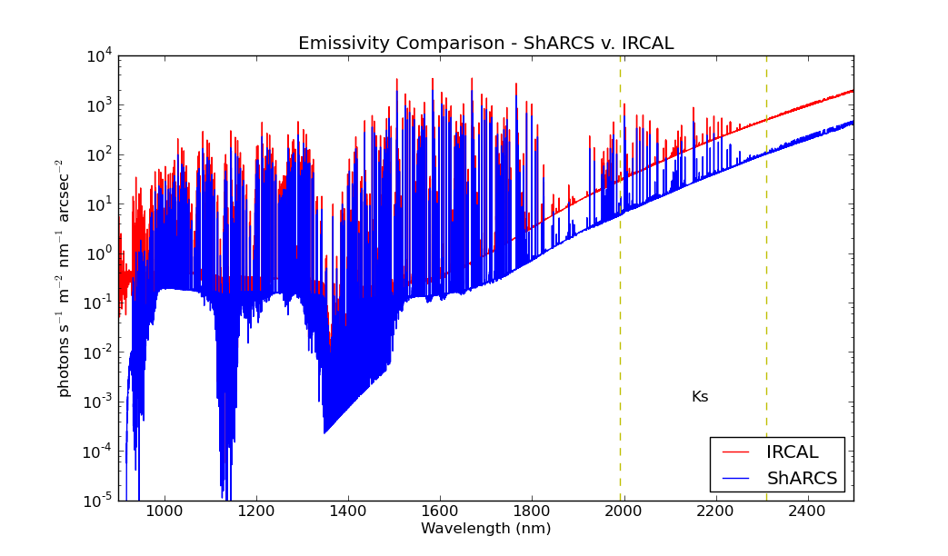
The new system will use the same filters as the current system (IRCAL filters) and all numbers presented below assume a dust coating fraction of 3% of the area on optics outside the dewar. A worst-case summer time dome temperature of 291 K (18 C) and a coating degradation of 2.5% for aluminized surfaces is also assumed. Hence, the system should perform better on colder nights and after the primary mirror is re-coated (scheduled for 2014). Strehl ratios for all calculations are derived from models detailed in [6].
 |
Limiting magnitudes - point sources
|
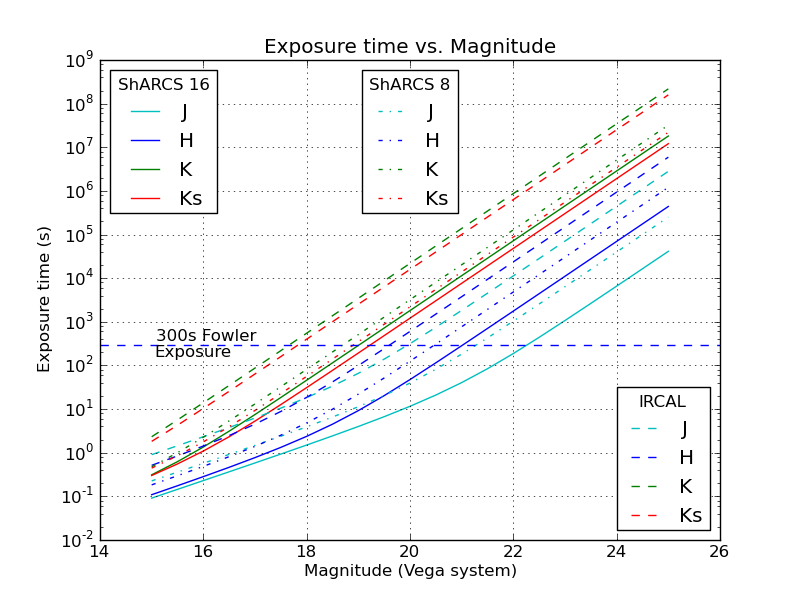
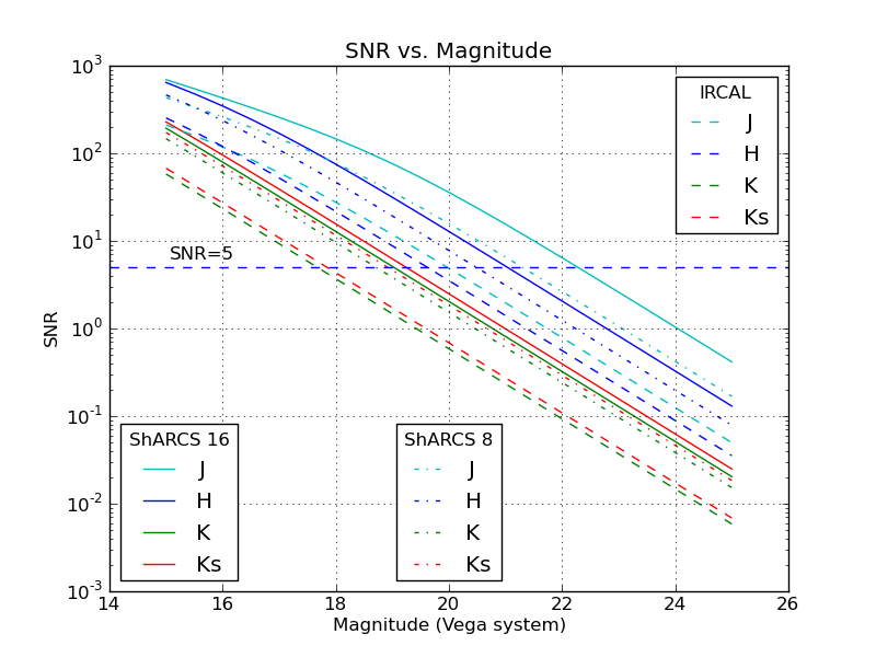
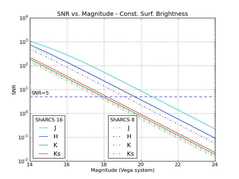
Graphically, the results for point sources for current and new systems are displayed in Figures 2 and 3. Figure 2 illustrates the prediction that ShaneAO will be faster by a factor of 10-13 in reaching a fiducial SNR. Figure 3 is a representation of Table 2. The curves change slope at the transition between sky background noise dominance (fainter sources) and source photon Poisson noise dominance (bright sources).
 |
 |
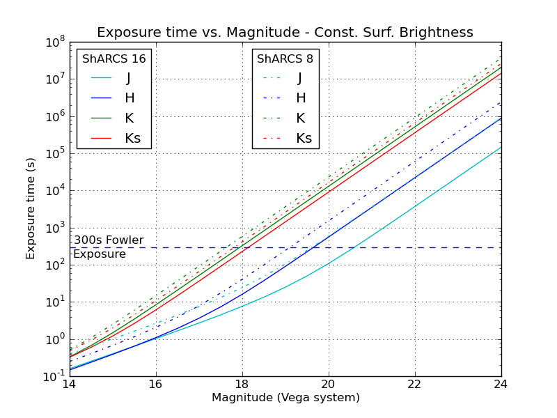
Limiting magnitudes - constant surface brightness patches
|
 |
 |
Limiting magnitudes - surface brightness profiles
TBDSpectroscopy
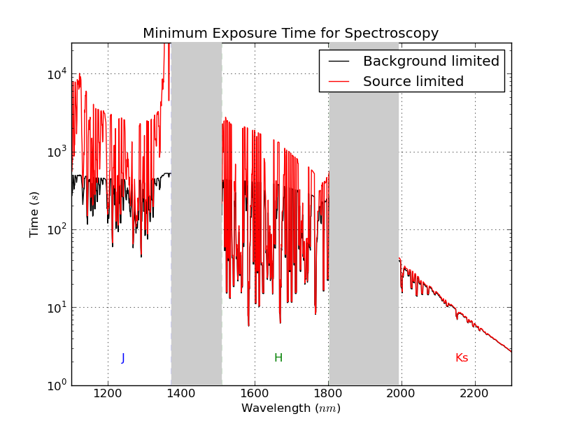
Figure 6 shows the minimum amount of exposure time needed to no longer be limited by the detector noise and background noise.
 |
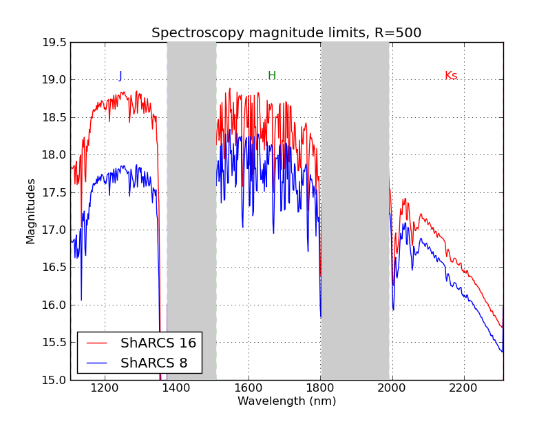
Limiting magnitudes in the JHKs bands for spectroscopy with the ShARCS 8x8 subapertures (the initial configuration) and ShARCS 16 setup are shown in Figure 7.
 |
Polarimetry
This section will contain a description of the polarimetric capabilities of ShaneAO along with its associated predicted limits.ShARCS Detector Specifications
1. aperture diagonal length 2. Per 340 s Fowler-32 read |
References
Questions: srikar at ucolick dot org
Modified: 2013-10-10 22:43