2.1 Optical Design Philosophy
DEIMOS optical design parameters follow from the optical performance goals. The overriding goals are good pixel scale for imaging and accurate sky subtraction, high dispersion for good sky subtraction on faint objects in the red, and wide camera FOV for long spectral coverage and long slit length on the sky.
The logic of the design unfolds as follows:
The choice of a reflective collimator was explained in Section 1.6. Given this choice, the curvature of the collimator focal surface must approximately match the field curvature of the telescope focal plane, which is 83.6-in. The collimator focal length should be equal to or slightly longer than this value. At the same time, a longer collimator means a bigger beam for spectroscopy, but it also drives one to bigger gratings. We have adopted the longest collimator focal length commensurate with the use of 6-in by 8-in gratings, which is our workhorse size. However, the 1200-line grating in the red is used at high tilt. This grating will probably therefore be an 8-in by 12-in (vignetting at the grating is discussed in Section 2.6). The current collimator focal length is 86.5-in, and the maximum beam diam eter for an 11.0 m Keck primary (tip to tip) is 6.33-in.
With collimator focal length frozen, the camera focal length follows from the desired pixel scale. The target value above of 0".15 per px (for imaging) would require a 12.0-in camera. We found that high optical quality was difficult to achieve at that short a focal length, the design containing a large, thin, and difficult to fabricate element. Key glasses also proved unobtainable. Lengthening the focal length to 15.0-in solved these problems without losing too much valuable field of view in the telescope focal plane. With a 15.0-in camera, the f-ratio for imaging is f/2.36 for an 11.0 m tip-to-tip primary, and the scale for direct imaging is 0.119" per pixel. The camera's (underfilled) optical f/ratio for spectroscopy is about f/1.39 for the most extreme grating set up.
Although this scale is a little finer than needed for direct imaging, it is actually well
matched to the most demanding application, namely, good sampling in the red at high dispersion. High anamorphic demagnification in the red reduces the apparent image size (in
the direction of dispersion) by a factor of ~1.7 with a 1200-line mm-1 grating at 8000 Ĺ.
Table 1.4 shows that there are then only 2.7 px across a 0".50 slit at this setting, which is
about right. Our primary scientific goal of good sky subtraction of bright OH lines will
also be helped with a modest degree of oversampling. It would appear that an optimum
design for a faint-object spectrograph on a big telescope at a good-seeing site leads inevitably to the use of rather high dispersion and fine pixels, a conclusion that was not initially
expected.
2.2 Camera 2.2.1 Camera Design with a 15-inch Focal Length and 11.4 Acceptance Angle
A camera design meeting the above specifications has been developed by Epps and it
is described in his report of May 2, 1994 (Design No. 8622). This report is attached as
Appendix B. This is not quite the final design we will build, but its characteristics and
image quality are close.
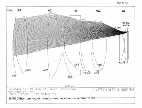
The optical layout is shown in Figure 2.1, and the system prescription is given in Table
2 of Appendix B. The camera has 9 optical elements in 5 groups and 4 coupled surfaces.
When used in spectroscopic mode with a (7.0 by 9.33)-in elliptical entrance pupil, the
camera shows an rms image diameter of 18.4 5.6 µ (0".13 FWHM) averaged over all
field angles and colors without refocus, and 21.0 µ of rms lateral color. This performance
is substantially better than the LRIS-red design on Keck I. The passage of rays at the edge
of the FOV is also shown in Figure 2.1.
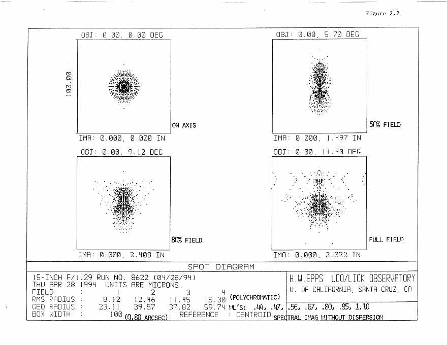
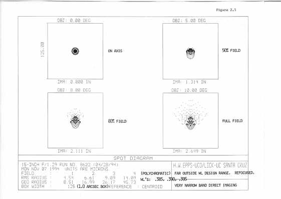
Spot diagrams with the large spectroscopic entrance pupil (7.0-in by 9.33-in) are
shown in Figure 2.2. In this and following similar figures, full field is 11.4 radius. Each
square is 0".80 on a side. All colors (listed at lower right) have been superimposed as if
for direct imaging. This application, which Epps calls "spectral imaging without dispersion," is more severe than real imaging since the spectroscopic pupil is used and the band
pass is very wide. It is also more severe than real spectroscopy since all colors are
superimposed and suffer from lateral chromatic aberration. Nevertheless the largest rms
radius is only 15 µ, or 0.20" FWHM.
Camera performance is summarized quantitatively in Table 3 of Appendix B, which
gives rms image diameters in spectroscopic mode versus color and field angle. For good
sky subtraction, an important criterion is constancy of point-spread-function over the field.
We have therefore tried to balance the aberrations uniformly, without attempting super
images in the center of the FOV at the expense of poor images at the outer edges. This is
also sensible for single-object spectroscopy, as spectra of single objects cover many field
angles. Uniformity of the PSF also means that the performance for wide-field imaging is
also fairly uniform over the field.
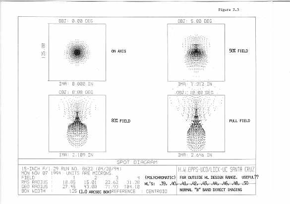
Direct imaging in the photometric "B" band is an anticipated application which takes
the camera far outside of its primary wavelength design range, into the blue. Figure 2.3
shows polychromatic "B" band images at 4 field positions, containing light at 9 wave
lengths from 0.39 µ to 0.50 µ. The superimposed box is 1.0" (8 px) on a side. The camera
has been refocused 75 µ "outward" to the best compromise detector location. The worst-case rms image radius is 31 µ or 0.42" FWHM at the edge of the field. Residual axial and
lateral color effects are apparent.
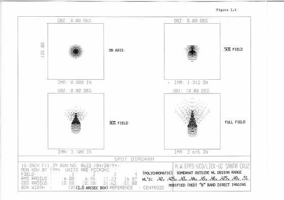
Considerable improvement is seen in Figure 2.4 which shows corresponding images in
a modified (red) "B" band which contains light at 9 wavelengths from 0.42 µ to 0.51 µ.
The net effect is a shift of about 250 Ĺ to the red. The images now show a worst-case rms
radius of only 17 µ or 0.23" FWHM at the edge of the field, with 100% of the light con
tained within an 0.83" diameter.
To summarize, except perhaps at full field in the very best seeing, we do not believe
that camera design aberrations will be apparent in use. The factor that limits the color
range is change of focus in the blue. The camera actually continues to make good monochromatic images as far down as 3900 Ĺ, but focus is ~200 µ away from nominal. For
some narrow-band applications (e.g., narrow-band imaging) this might be acceptable. As
an example, Figure 2.5 shows very narrow band (100 Ĺ) images centered at a wavelength
of 0.39 µ.
The basic design has good control over distortion. The main requirement for low distortion comes from the potential drift-scanning mode, which means that stars would drift
through the telescope focal plane perpendicular to the long dimension of the field of view.
The design of the CCD mosaic (Figure 1.6) allows drift-scanning on one-half of each
array, on the side on which the natural read-out direction follows the motion of the stars.
For effective drift-scanning, we require that the image of a star stay on the same row of
pixels to within 0.5 px (0".06) while it traverses the detector (4096 px) and that it traverse
the detector at the mean rate. This places limits on the distortion of the Ritchey-Chretien
focal plane of the telescope, the collimator, and the camera. The camera design has good
control over distortion, so we are sure that this aspect will be tractable. (The end-to-end
distortion of the system with respect to drift scanning is discussed in Section 2.9.)
2.2.2 Filters
Filters are located in the converging beam in front of the field flattener. This has the
desirable effect of making them small (standard 6.5-in filters from Schott will do), but
transmission will vary somewhat over the field because of the variable tilt of the beam.
Rough estimates of this effect indicate that it is tolerable, but this needs to be checked.
Interference filters cannot be used at all. The filters have to be of the same optical thick
ness to within 0.005-in. The exact thickness will be set by the thickest filter, which is the
B band. The final prescription for B has not yet been chosen, but the thickness will be of
the order of 0.5-in. This can be accommodated in the final optical design.
The complement of filters at first light will include Johnson B and V, Cousins R and I,
and one order-blocking filter (TBD) on each side. A clear glass "dummy" filter will also
be supplied for spectroscopy. All filters will be anti-reflection coated. There are a total of
7 filter slots on each side, of which two slots at each end (4 filters per side) are easily
accessible by the user. Filters carried in the two beams can be different, offering added
flexibility.
2.2.3 Camera Optical Materials and Camera Transmission
Material selection is perhaps the most subtle aspect of the camera optical design. The
issues of internal transmission and availability must be considered carefully, as well as the
ability of possible material combinations to effect acceptable axial and lateral color correction. The process is iterative in that a tentative design must be developed thoroughly to
determine whether or not it is optically workable. Thereafter one calculates expected
internal transmission and inquires about availability. Often it occurs that the design falters
at that point and must be completely redone.
A large fraction of the positive power in the DEIMOS camera is provided by CaF2 for
which there is no known substitute obtainable in the required sizes and at reasonable cost.
At least one other positive lens element of a different material is required to attain color
correction over the camera's full (0.44 to 1.10) µ spectral range. Ohara FK01 was chosen
for that purpose as the best of several alternative possibilities. Beyond that a protracted
optical design process produced the combination of negative lens elements and materials
seen in Figure 2.1, which also shows the fractional optical power contribution of each of
the lens-element groups.
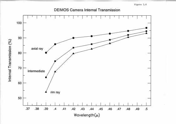
The expected internal transmission for this material combination is shown in Figure
2.6 as a function of wavelength. It has been assumed that the CaF2 elements and the fused
silica dewar window do not absorb in this spectral region which is a good assumption,
even though a 9.1-in axial path length of CaF2 is used. No filter is included.
One notes that the internal transmission depends upon the particular ray path through
the camera. Three paths are shown: 1) the axial path; 2) a typical intermediate path; 3) the
extreme rim-ray path. The internal transmission varies from 83% to 91% at the 0.44 µ
extreme blue end of the design wavelength range. Blueward of 0.42 µ it rolls off quickly.
It varies between 54% and 80% at 0.39 µ
The "worst absorption offender" is the deep negative meniscus of SSK5 on the leading
side of the triplet. As yet, no acceptable substitute material has been found. However, the
entire optical design will be restudied prior to ordering optical glass in an attempt to find
more transmissive materials.
The most difficult material to obtain is the 3 large pieces of CaF2 (each beam), which
are made in 15-in diameter sizes only by Optovac in North Brookfield, MA. The material
is grown as a synthetic crystal in "boules" (sometimes called "ingots") which are cylindrical with a 3-in height topped by a 2-in tall cone shape. The growing and annealing period
is approximately one month, followed by about 2 weeks for cleanup, inspection, and analysis. There is no way to predict whether a given growth/inspection cycle will be successful, and failures do occur.
A single 14.4-in boule was ordered as a proof of procedure from Optovac at a cost of
$25,000. That boule has been delivered successfully to the Lick Observatory Optical Laboratory and looks excellent. Having produced this boule at a fixed price cost of $270 per
pound, Optovac has now agreed to provide subsequent boules on a price-by-volume basis
at a cost of $200 per pound for the boule sizes we need. This is detailed in a letter from
Optovac General Manager Mr. Rob Sparrow, dated 04/28/94 to Harland Epps, which is
reproduced in Appendix B. The delivered price for the three boules for each camera will
be about $52K plus tax.
Optical glasses should not be a problem. Ohara has submitted a firm quotation (Q4
8148) for all of the glass required to build up to three copies of camera lens Design No.
8622. Their quotation of May 12, 1994 is reproduced as an addendum to Appendix B.
The total weight of the finished camera optics will be approximately 151 lbs (each
beam).
2.2.4 Camera Optical Fabrication Plan and Risks
1.) Fabrication of Optical Elements: All camera optical elements will be fabricated in
the Lick Observatory Optical Laboratory. We have had considerable experience in fabricating similar refractive systems. For example, we made the camera lenses in the LRIS
and Norris spectrographs, the Carnegie COSMIC spectrograph, the Lick Observatory Kast
spectrograph, and the recent "LAGOS" aspheric element for the Livermore Adaptive
Optics Program. The Norris and LRIS systems were most similar to DEIMOS. They had
fewer elements and were smaller in diameter than the DEIMOS elements (8 to 9-in) , but
they contained difficult aspherics as well as CaF2. The spherical surfaces of the present
design pose no special problems. The principle manufacturing concerns are the strongest
aspheric on the leading surface of the first camera element and the fabrication of the CaF2
elements, which are sensitive to thermal shock.
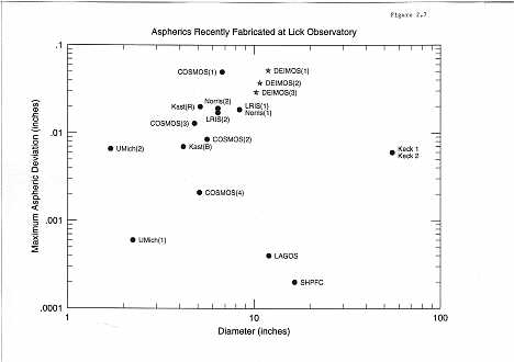
The strong aspheric on the 0.59-in convex sagitta of the 11.64-in clear-diameter first
@LAK07 element has a maximum aspheric deviation (MAD) of 0.0465-in. This is comparable to but a little larger in size and maximum aspheric slope gradient than aspheric
surfaces that have already been produced at Lick. The two other aspherics have lesser
amplitudes on smaller surfaces which are nearer to the focal plane, and residual slope
errors are less important. Figure 2.7 shows MAD vs diameter for aspheric surfaces successfully fabricated at Lick, compared with the DEIMOS aspherics.
We plan to fabricate all aspherics by using a plunge-grinding technique with an
aspheric tool. We have used this method successfully and have perfected a method of
machining such tools to an accuracy of 1 µ. After plunge grinding, the surface is fine-ground and ready for polishing, which we will undertake with a flexible lap. A sum of
$60,000 has been included in the budget to finance further preliminary tests on aspheric
grinding and gluing.
Aspheric surfaces will be tested using our profilometer system. This has recently been
upgraded and is now much more reliable. It has been used successfully to make other
aspherics and the Keck I f/15 secondary mirror and is now being used on the Keck II f/15
secondary. It measures to an accuracy of better than 1/10th wave, which is roughly 10
times better than needed.
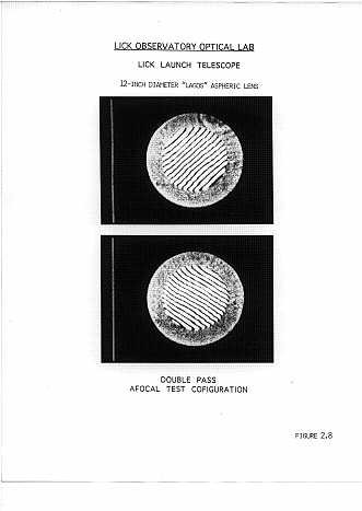
Figure 2.8 shows a double-pass interferogram of the 12-in diameter "LAGOS"
aspheric lens, which was produced in our optical laboratory entirely by testing with profilometry. Its nearly defraction-limited figure atests to the skill of our opticians as well as
the reliability of our profilometer and its data reduction system.
The second fabrication challenge is the 6 CaF2 blanks (3 per camera). We have previously polished CaF2 elements as large as 6 inches in diameter for Kast, and we have han dled 9-in diameter CaF2 lenses for LRIS and Norris. We believe that the same techniques
will be adequate for DEIMOS. A major concern is edging and generating, which are particularly dangerous from the standpoint of thermal and mechanical shock. We are considering having this work done at Optovac in order to minimize financial risk to the project.
The budget contains $112,000 to fund various upgrades to our optical fabrication and
testing equipment. These include two polishing machines, a spherometer, generating
wheels, and partial payment for a new generating machine.
2.) Coupled Elements: A second area of concern is the 4 coupled optical joints.
Again, we have had experience with such joints in the LRIS and Norris designs (two each)
but the maximum size is only 8 inches in diameter rather than 14 inch as here. A problem
occurs with the bonding of optical glasses to CaF2 in that the differential coefficient of
thermal expansion of CaF2 is quite large, roughly 10-5 per degree C. The lens will experience a large total temperature difference of some 30 C between Santa Cruz, where it is
fabricated, and the top of Mauna Kea, where it will be used. Therefore the coupling
medium must be compliant.
Because of the large thermal expansion coefficient of CaF2, we have opted for a coupling material that exerts no forces on the coupled surfaces. This means that each lens element will have to be self supporting (see next section). We have performed aging and
transparency tests on several materials and find that only one, Sylgard 527, is gelatinous
after curing, is easy to apply without voids and bubbles, and appears to be transmission
stable with time.
Optical transmission tests were made using 1 mm quartz microscope slides with a
thickness of .025" of Sylgard 527 in between. This is equivalent to roughly 15 glass-to-
glass interfaces. The same samples were measured from .250 µ to 1.10 µ at Lick Observatory and at Optical Data Associates in Tucson, Arizona. The results show that the internal
absorption is about 5.0% at .300 µ, 2.5% at .320 µ, and essentially zero redward of .350 µ.
This gives a worse-case coupling loss of 0.34% per interface at .300 µ.
Mechanical loading tests were made on a pair of 2.9-in square by 3/8 inch thick pieces
of glass bonded with .001 inches of Sylgard 527. By clamping the bottom piece and
applying force horizontally to the upper one, we found that 8 pounds of force, or about 1.0
pound per square inch, gave a lateral displacement of .003 inches. Five pounds of force
were applied and left for 24 hours. When released, the upper glass returned to its rest
position indicating that the Sylgard 527 is elastic and had not taken a "set".
Thermal tests were performed on a 14-in diameter by 3/4-in thick piece of aluminum
bonded to a 12-in wide by 9/16-in thick piece of Pyrex with .002 inches of Sylgard 527. It
was put in the freezer at -20 C for 15 hours. After removing, letting it come to ambient
temperature, and inspecting, no evidence whatever of thermal damage was visible. The
thermal coefficient of expansion of aluminum is 24 x 10-6 per C and Pyrex is 3 x 10⁻⁶ per
C and since it was subjected to a temperature differential of 40 C, the change in length
per unit length was 840 x 10-6. The worst case DEIMOS glass pair is CaF2 and KZFS01,
and the projected temperature differential is 30 C. This gives a change in length per unit
length of 420 x 10-6, which is half that for the tested sample. If further lifetime testing
confirms both optical, mechanical, and thermal stability, an adequate coupling material
will have been found.
3.) Lens Support; Lens Cell: Support of the camera optical elements does not in general pose a problem except for the sixth @KZFS01 element, which is thin. As the design
is not yet final, it is our goal to either eliminate or thicken this element if possible. In the
meantime, we have conducted a finite-element analysis of this element, as described in
Chapter 5. The surface deviations of element 6 due to gravity, when held at three points,
may be fit to within 95% with the third order polynomial,
D = -0.2013 - 0.0168 x2 + 0.0892 y + 0.0191 y2 + 0.0006 y3 - 0.0025 x2y,
where D is in microns, x and y are in inches from the optical axis, and gravity is in the negative y direction. The dominant term is the linear term in y, which deflects the images in
the focal plane by at most 0.5 µ. The higher order terms focus or defocus the images on
the order of 1% in the rms spot diameter. Both of these effects are negligible.
2.3 Collimator Mirror
The collimator is an optically challenging element as it must work over a field of view
of radius 9.4 as seen from the vertex of the collimator. This large angle is required for
wide-field imaging as well as for long-slit spectra.
Traditional off-axis collimators do not offer this level of performance. During the
design of LRIS, Epps developed a principle for reflecting collimators that roughly
matches their field curvature to the telescope focal-plane curvature. As explained above,
this means that we need a collimator focal length comparable to the 83.6-in radius of curvature of the Keck Nasmyth field. Our current choice is 86.5-in, that maximizes the size
of the pupil which can be accommodated on a 6-in by 8-in grating (see below).
The final element of the collimator design is the choice of conic constant. The DEIMOS collimator should be slightly ellipsoidal. We have verified that this basic collimator
approach will work but have postponed the precise choice of conic constant until the rest
of the design is finalized. We are currently using a Conic Constant A2 = 0.75 as a preliminary value.
The collimator is 46.3 inches in diameter and approximately 4-in thick with a 4-in central hole for aligning the spectrograph on the Nasmyth platform. It weighs approximately
400 lbs. The blank will be Zerodur to minimize testing turnaround time. The collimator is
fairly fast, f/1.87. It will be generated outside and then polished in the Lick Observatory
Optical Laboratory on our 48-in Strasbaugh machine, which is outfitted for such aspherics. Testing will be done on the profilometer. The final "buy-off" verification test will be
done in autocollimation against our 40-in reference flat. A small all-spherical null lens
may be required.
The collimator mirror will be silver coated with the same coating method used for the
optical segments on Keck II. It will fit within the coating chamber on Mauna Kea used for
the segments and will be coated on the mountain.
2.4 Gratings and Flat Mirrors
The spectrograph is designed for a standard grating size of 6-in by 8-in, but one grating slot
can take 8-in by 12-in gratings, which will be desirable for a 1200-line mm-1 grating used at high tilt in the
red (see Vignetting, Section 2.6 below). The precise choice of
gratings is still TBD, but the table below offers a strawman complement. The last column
shows whether the grating is currently available in the Milton-Roy catalog. It is likely that
we will require at least one new master, as the 830 line mm-1 grating is in some ways the
most useful, but MR offers no suitable choices. Several other 600 and 1200-line gratings
in both large and small sizes are available in the MR catalog. Gratings will probably be
aluminized, but we will also look into overcoated silver.
The flat mirrors for direct imaging are somewhat oversized to avoid all vignetting in
the direct imaging mode, which could adversely affect photometric accuracy. Their size is
7-in by 9-in, and they are coated with silver.
In the normal observing mode, there will be one flat mirror and two gratings in place
on either side. As for filters, gratings on the two sides can be different to add flexibility.
2.5 Other Optical Elements
A 35-in diameter flat window sits immediately behind the focal plane and seals the
spectrograph from the environment. We have money in the budget for this element, but
we are hoping to find a used window from one of the laser projects at Livermore. This
element does not have to pass ultraviolet light; BK7 or something similar is satisfactory.
Since it is close to the focal plane, the surface tolerances are fairly low. Surface errors will
affect the astrometric solution from the focal plane to the detector, but these terms will be
constant and can be measured. The blank has two small cutouts across a diameter to allow
light to pass from the tent mirrors to the two gratings. It also has an 8-in hole in the center
which can be unplugged to allow for collimation and alignment on the Nasmyth platform.
The tent mirrors that divide the telescope focal plane into two beams comprise the last
optical elements. They are simple flat mirrors 18-in wide, 16-in long, and 2-in thick, made
of Zerodur. There is an 18 bevel at one end to form the Vee. We will have them fabricated
outside. The support system for these mirrors may be active to steer the beam during
Flexure Compensation. If so, a range of ~50" in tilt and tip would be required (see Chapter
7). These mirrors will be silver coated at Mauna Kea.
2.6 Vignetting
Vignetting occurs at three locations: the tent mirror (both incoming and outgoing
beams), the grating, and the camera. Camera vignetting has been studied in an earlier
design report by Epps. Because of the wide camera mouth and oversized third element,
camera vignetting is comparable to or smaller than typically found in astronomical spectrographs despite the wide FOV. The worst case occurs for a highly elliptical pupil result
ing from high grating tilt with the 1200-line mm-1 grating in the red region. For a pupil
axis-ratio of 1.7 (8000 Ĺ) and a star on the camera axis (center of active focal plane), a
spectral element at the very end of the spectrum suffers only a 13% loss. This is barely
increased at the top and bottom of the slit. Loss is slightly greater for stars at the edges of
the focal plane, but since the FOV is so narrow compared to the detector width, this effect
is marginal. Altogether camera vignetting is about half that in LRIS.
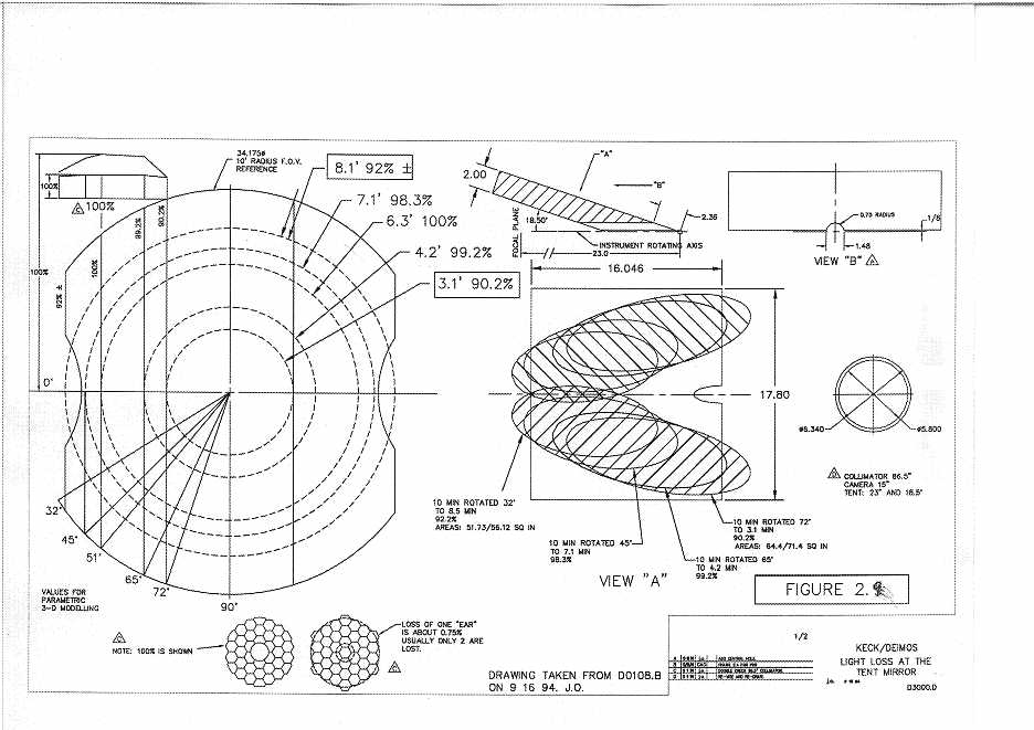
Vignetting by the front surface of the tent mirror is the most important factor in laying
out the spectrograph. The tent mirror edges help to define both sides of the focal plane
FOV, as shown in Figure 2.9. At the inner edge near the telescope axis, there is a slow
cutoff due to one front edge of the tent mirror combined with a sharp cutoff due to the
back side of the tent mirror where beams enter the spectrograph. At the outer edge of the
focal plane, there is a second slow cutoff due to the other edge of the tent mirror, plus a
sharp cutoff of entering beams caused by the camera body and grating slide. The layout
process involves getting each pair of cutoffs separately to coincide. A vignetting calculation for the focal plane caused by these elements together is shown in Figure 2.9. Contours of equal vignetting run parallel to the slit. The fully unvignetted FOV is a strip 2'.1
wide extending from radius 4'.3 to 6'.4. However, the vignetting is extremely benign, and
the usable area extends inwards to 3'.1, where vignetting reaches 10% before cutting on
sharply due to the back edge of the tent mirror. The usable area also extends outward
above and below the camera notch to a distance of 8'.5, where vignetting is 8%. At this
point the field is cut off by the grating slide. The slight variations in vignetting caused by
rotation of the odd-shaped Keck pupil (1% or less) can be easily removed for photometric
purposes in direct images by normalizing to the local sky.
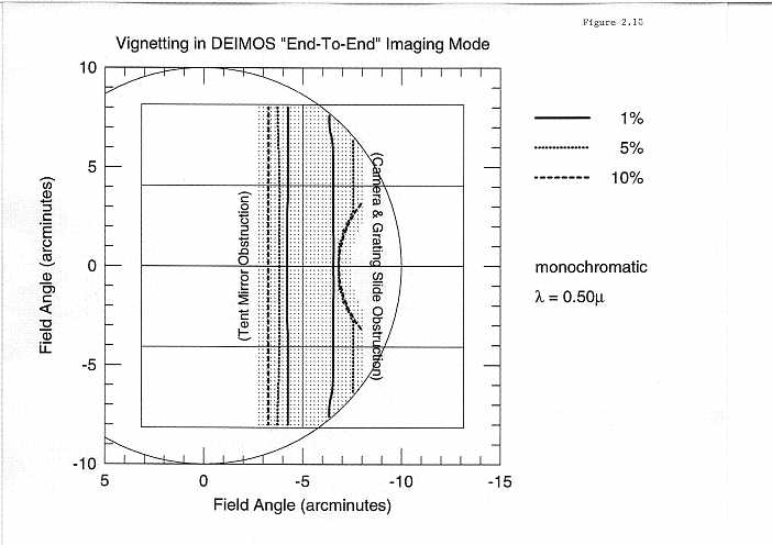
The vignetting of a more recent "end to end" model (including the telescope, collimator, and camera) is shown in Figure 2.10. Raytraced points where light reaches the detec
tor are marked with a dot. The detector, shown centered at 5', is outlined, as well as the
telescope's full 10' field of view.
Vignetting also occurs at the grating. The design has a beam diameter as large as a 6-
in by 8-in grating can possibly hold. For reference, the beam diameter from tip to tip of
the primary (5.01 µ) mirror (11.0 m) is 6.33-in, while the ruled width on the grating (from
Milton Roy) is 6.10-in. That means the tips of the primary mirror will overhang the ruled
area slightly. For vignetting calculations we have defined a so-called "vignetting radius"
of the primary that circumscribes all tips except the outermost ones (see Figure 2.11, also
Table 1.1). Each tip contains 0.75% of the light. The beam diameter of the vignetting
radius is 5.79-in and thus fits well within the ruled area.
The amount of light lost widthwise on the grating will be negligible (less than 1.5%)
as long as the pupil is kept in good alignment on the grating. Our tolerance for this is
0.05-in. Among other things, this translates into a tolerance for how well DEIMOS must
be aligned with the telescope optical axis on the Nasmyth platform, and thus a tertiary collimation accuracy of 2'.0, or approximately 0.15-inches in the axial position of the ter
tiary along the telescope axis. Because this tolerance is tight, we have built in a way for
the observer to monitor it using an out-of-focus direct image taken by removing the filter
from the beam. The resultant images are ~170 px across. Scribe marks on the flat mirror
will allow referencing the out-of-focus pupil image to the exact center of the flat. The
gratings and flat mirror will be installed so that their centers accurately coincide when
inserted into the beam, so that the flat alignment will also check the gratings.
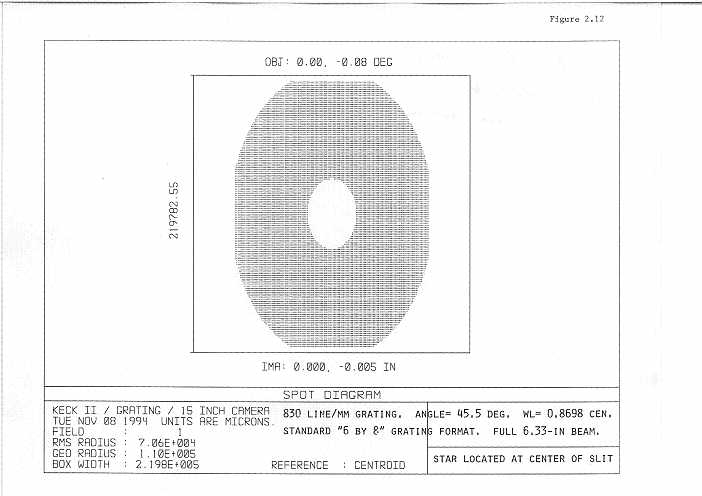
Lengthwise, the amount of light lost for a star at the middle of the slit on the grating
can be estimated via the vignetting values shown in Figure 2.12. One finds that there is
essentially no additional loss with a 6-in by 8-in grating up to beam ellipse ratios of 1.38.
This covers all tilts used by the 600-line mm-1 and 830-line mm-1 gratings. Light loss
with the 1200-line grating is worse and reaches an average of 10% for all pupil orientations at 8000 Ĺ (beam ellipse ratio of 1.67). Since this is a primary use of the spectrograph (high dispersion in the red region), we have built in the option of using a larger 8-
in by 12-in 1200-line mm-1 grating by including one larger grating slot.
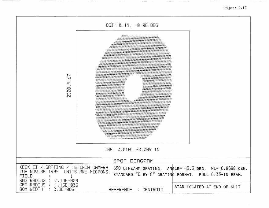
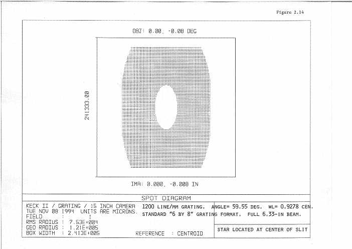
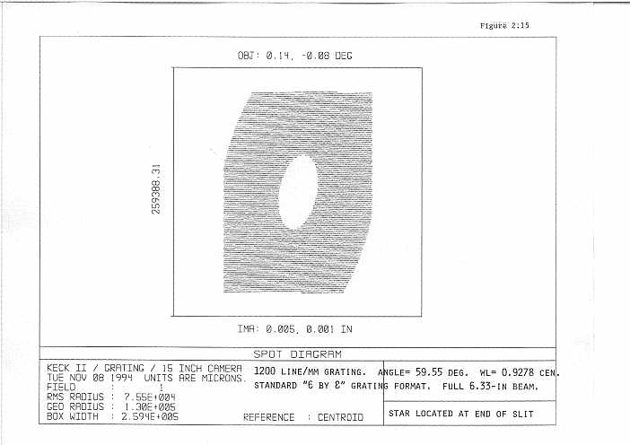
In order to further visualize potential light loss at the edges of a standard 6-in by 8-in
grating we show a full 6.33-in pupil envelope on an 830-line mm-1 grating set up at 45.4
for a 0.8698 µ central wavelength (the reddest tilt in Table 1.5). Figure 2.12 showed the
star at the center of the slit while Figure 2.13 shows the star at the extreme end of the slit.
The anamorphic factor as well as light loss on all 4 edges of the grating are apparent. The
off-axis star image exhibits pupil rotation as expected. Figure 2.14 and Figure 2.15 are the
analogous pictures for the more extreme case of a 1200-line mm-1 grating set up at 59.55
for a 0.9278 µ central wavelength. It is obvious in this case that the light loss is unacceptable and that a larger (8-in by 12-in) grating is required.
If this is deemed necessary, it can be accommodated by moving the spectrograph back
from the nominal focus on the Nasmyth platform by a few inches. This would allow the
grating slide to clear the elevation bearing and would permit two wide slots (see Figure
5.2). This option will be considered before the choice of final design. The cost difference
between a 6-in by 8-in grating and an 8-in by 12-in grating is roughly $20,000, or $40,000
for two beams.
Given that the full 6.33-in pupil is used in these figures, it would appear that use of a
small 6-in by 8-in size for both the 600-line mm-1 and 830-line mm-1 gratings would be
acceptable from a light-loss standpoint. However, we raise the possibility in Chapter 7
that variable pupil illumination may contribute to flat fielding errors, in which case a larger
8-in by 12-in size may be needed for the 830-line mm-1 grating. This would require two
wide grating slots, not just one as currently planned.
2.7 Optical Coatings and Ghosts 2.7.1 Collimator, Tent Mirrors, and Flats
As noted, all mirrors in DEIMOS (except the ruled gratings) will be silvered since the
instrument is to be used on Keck II. The collimator, tent mirrors, and flat mirrors can be
coated in the Keck II coating chamber. We will use whatever silver overcoating method is
adopted for the primary mirror.
2.7.2 Anti-Reflection Coatings
There are a total of 16 air-glass surfaces in the entire optical path, including the win
dow, filter (always in), dewar window, and field flattener. High throughput depends on
efficient optical coatings.
There are two basic approaches to coating the transmissive elements, and both will be
explored. The first is multi-layer interference coatings. A copy of the camera design was
sent to ZC&R, including the dimensions and indices of refraction of all elements. A bid
was received to coat all elements to a reflectance R Ł 2.0% averaged from 0.44 µ to 1.1 µ
and 0-45 incidence, and R Ł 1.0% at normal incidence. Allowing for the steepness of the
angle of incidence at each surface and using Epps' estimated glass transmission of 0.95
beyond 0.51 µ yields an average total throughput of 78% for all transmissive elements for
spectroscopy (not counting the window, see below).
The second approach would use Sol-Gel coatings of the type used on HIRES. These
are manufactured by Livermore National Laboratory. Two types are available. A standard single-layer coating, which is normally applied to fused silica, has an average R Ł 1%
over the entire bandpass. The second type is a 2-layer sol-silicone coating, which gives a
spectacularly low R of ~0.25-0.50% over a broad band when used on either BK7 or fused
silica. The performance of these coatings is not known at high incidence, nor whether all
our glasses can be treated. However, it does seem clear that applying one or another type
of Sol-Gel to at least a few elements such as the clear window and the dewar window
would add several percent to the transmission over and above AR coatings.
The bottom line is that we see a reliable way to guarantee a mean transmission of at
least 73% for all transmissive optics (1% for the window is now subtracted), and that Sol
Gel on a few if not all elements should increase this by several percent.
2.7.3 Ghost Images
Ghost images are always a concern in refracting astronomical optics. Reimaged back
reflections of light scattered by the CCD detector are of particular concern, as the detector
reflectivity is typically in the 5% to 10% range. We have attempted to mitigate against
these back-reflections by controlling the incidence angle of the marginal ray at each air-to-
glass surface in the camera, so as to avoid normal incidence.
We have calculated the far-field surface brightness of back-reflected ghosts (G) which
would be produced in Camera Design No. 8622 by a 0 magnitude star. Our "G" values are
given in units of magnitudes per square arcsec. We assume that the residual reflectivity of
a typical air-to-glass surface boundary is 0.015 and that the CCD detector has a reflectivity
of 0.08.
It turns out that the reflection off of the trailing surface of the vacuum window is the
worst offender. It produces a halo some 19 arcsec in radius with G = 15.0. The leading
surface of the vacuum window gives G = 15.8, while the leading surface of the large negative meniscus SSK5 element gives G = 15.6. The rest of the surfaces (including the filters) contribute negligibly to the ghost image. The total integrated surface brightness from
all of the surfaces taken together is G = 14.1 magnitudes per square arcsec. We believe
that this is a pessimistic estimate in that careful attention to the coatings on the worst offending surfaces and on the detector can reduce this effect by one magnitude or more.
2.8 Assembly and Collimation
We assume for this section that the individual optical elements have been tested. We
also assume that assembly of the camera optics will be routine. That is because the individual elements will be carefully edged and centered, and the cell will be made with hard
stops and no adjustments. We will check that the optical design will function properly at
20C, the assembly temperature in Santa Cruz, with only a simple offset in focus position
to the operating temperature of approximately 3 C. With these assumptions, the camera
optics should go together with no degrees of freedom. We will illuminate the camera with
parallel light in the lab to verify correct manufacture.
All optical components will be assembled in Santa Cruz, and the spectrograph will be
fully tested using its internal light sources and possibly other test sources yet to be
devised. We have walked through the assembly procedure, and a provisional summary is
given in Appendix C. Insofar as possible, assembly of the spectrograph will be done with
measuring devices, not light beams. The main idea is the use of tooling balls at key locations: at the vertex of the collimator mirror, the vertex of the focal plane, and three tooling
balls at the periphery of each of the slitmask holders. The latter serve the dual purpose of
helping to position the mask holders in the focal plane relative to its center and of locating
the masks reproducibly in the slitmask cutter machine.
After the focal plane and slit masks are surveyed in, assembly then proceeds to the collimator mirror and from there to the tent mirrors, all of which are surveyed from the tooling balls in the focal plane. The camera location in three spatial directions and in angle is
not particularly critical since it accepts parallel light. It will be surveyed into the spectrograph frame with an appropriate jig cut to the right angle. The detector will be surveyed to the lens cell so that the two will be installed and aligned as a piece (except for
focus).
The one remaining element is the flat mirror. The critical parameter is the distance and
direction of the flat mirror from the tent mirror. We may survey in the grating tray holding
the flat relative to the rest of the focal plane as we did the slitmasks, or we may elect at
this point to use an autocollimation telescope or even a laser. We will not close the
mechanical design of the focal plane area until this item has been thought through.
At this point DEIMOS is properly aligned internally, and it remains only to locate it on
the Nasmyth platform. Recall from Section 2.6 that if the optical axis of DEIMOS is not
properly aligned with the optical axis of the telescope as reflected by the tertiary mirror,
the pupil will walk on the grating. Successful alignment is achieved when a) an on-axis
beam at the center of the telescope focal plane is reflected by the tertiary exactly 90 to the
telescope optical axis, and b) DEIMOS' axis is coincident with this beam.
To achieve this, the mechanical design allows one to sight through a hole from behind
the center of the collimator mirror, through the middle of the focal plane (the plug in the
window is removed), and off the tertiary mirror to the secondary and primary. With correct alignment, in an autocollimation telescope attached to the hole in the collimator, one
will see successively superimposed a fiducial cross-hair marking the center of the focal
plane, the center of the tertiary, the center of the secondary, and the secondary centered in
the primary. Furthermore, if the tertiary is properly located, this alignment will not be disturbed as the telescope changes elevation.
Note that the tolerance on the tilt of the tertiary mirror is approximately 2'. Requiring
also that the tertiary reflect by exactly 90 means that the tertiary has to be properly
located in the axial direction along the telescope optical axis to 0.15-in. These tolerances
are approximate and need to be checked by detailed calculation.
A final point is that the tertiary needs to service other foci as well as the right Nasmyth
platform, where DEIMOS is located. Therefore there will have to be coordination with
other possible instruments at the bent Cassegrains and the other Nasmyth platform. This
coordination will have to be supervised by the Observatory staff. We emphasize that
accurate collimation is an important assumption in the DEIMOS optical design and we
will not have much flexibility in adjusting to other instruments.
2.9 End-To-End Optical Performance
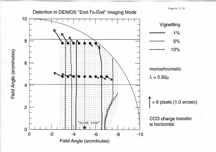
Relative distortion of the "end to end" system was investigated by assuming that a
"guide star" at the "on-axis" position (i.e, 5'.0 off-axis relative to the telescope) was purposefully drifted at a uniform apparent rate along the (horizontal) charge transfer direction. This is shown schematically in Figure 2.16. Initially two stars 4'.8 and 7'.8 off-axis
in the vertical direction had locations shown by the round arrowless dots. As the guide
star drifted to other lateral locations, the ideal optical system would have placed the off
axis star at the dots shown, from 3'.0' to 7'.0 in the lateral coordinate. The arrows show the
magnitude and direction of the actual position error in pixel units.
It is apparent that a large fraction of the error lies along the direction of charge transfer. The details of this complicated distortion will become the subject of further study as
the DEIMOS design develops, as it is clearly of vital interest with regard to the possibility
of effective drift-scan imaging. At this time it is not clear whether anything can be done to
improve the result shown in Figure 2.16. However, given that the total elongation of
images can be reduced by a factor of 2 by use of a mean drift rate it would appear that
usable images can be obtained at least up to vertical distances of 5' along the FOV in
drift-scan mode.
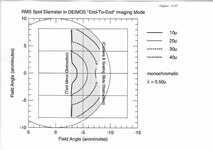
We now consider the optical "end to end" performance of the entire telescope plus
spectrograph in imaging mode. A first look is shown in Figure 2.17, where the contours
give the rms image diameters (in µ) over the imaged field. Most of the point spread is due
to the astigmatism of the telescope, with only a small contribution from the collimator and
camera.
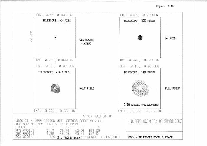
We conclude this section with a sequence of three figures which illustrate the image
quality separately of various components in the DEIMOS optical train. Figure 2.18 shows
images on the (curved) focal surface of the Keck II telescope. The telescope's "on axis"
image is obstructed by the instrument and is therefore not observed. The instrument's "on
axis" image is actually located some 5' off axis in the telescope's field of view. It shows a
small amount of astigmatism, as expected in a Ritchey-Chretien telescope. The astigmatism grows to an rms image diameter of 0.30" at the instrument's "full field" of view.
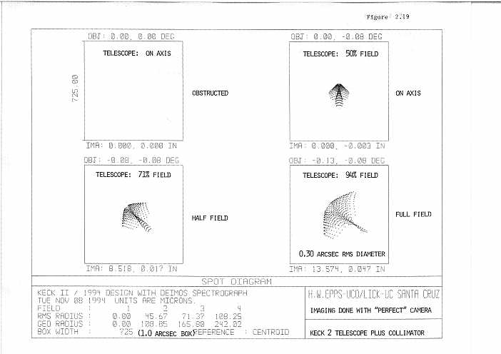
Figure 2.19 shows the telescope plus its (elliptical A2 = 0.75) collimator, reimaged at a
one to one scale by a perfect camera with no aberration of its own. It can be seen that the
images develop high order comatic "tails". However the rms image diameters do not
increase appreciably. Thus it can be said that the collimator contributes almost negligibly
to the system's aberration.
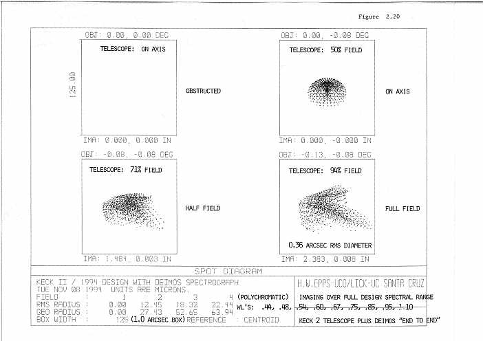
Finally, Figure 2.20 shows the full "end to end" imaging performance. The polychromatic images contain light at 9 wavelengths covering the full (0.44 to 1.10)-µ design spectral range.
The full effects of axial and lateral color are included, yet worst-case rms image diameter at full field has only increased from 0.30" (telescope alone) up to 0.36"
(full "end to end" system). Thus we conclude that the DEIMOS optics faithfully reproduce the telescope's intrinsic astigmatism remarkably well.
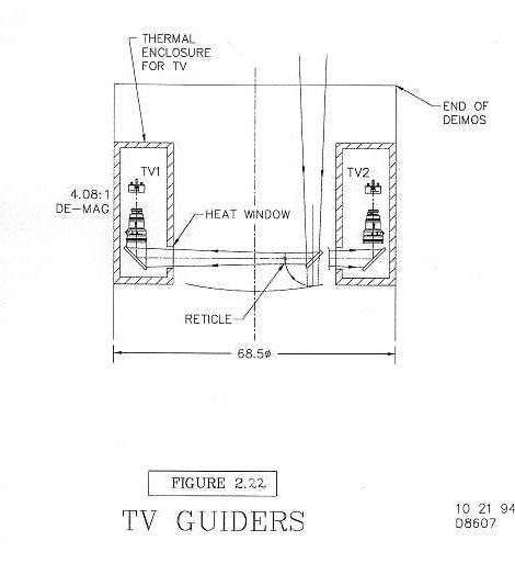
2.10 TV Guiders 2.10.1 Specifications
The current TV design is shown in Figures 2.21 and 2.22. There are several design requirements:
1) The TV system should provide accurate offset guiding to 0".05 rms with multislit
masks. That means controlling both telescope centering and DEIMOS position angle to
high accuracy. An error of 0".05 at the edge of the slitmasks translates to an error of 8".6
in DEIMOS Position Angle (PA). The instrument rotator drive is being designed with
enough resolution to maintain the angle to this accuracy with positional feedback, but the
desirable mode requires two guidestars.
The total field of view for a single TV should therefore be at least 5 arcmin^2. With this
field, at the Galactic poles where stars are sparsest, there will be at least one guide star
available 95% of the time. That means there will be two guide stars, one in each camera,
90% of the time, and no guide stars only 0.25% of the time. Two guide stars provide
insurance for guiding accuracy and also allow us to monitor telescope aberrations in real
time. A TV FOV of 5 arcmin^2 is a compromise between the desire to have two guide stars
all the time and the availability and cost of the TV optics and CCD detectors.
We are still studying the case of one guide star. As noted, at the Galactic poles this
will occur 10% of the time. Guiding successfully with one guide star depends on getting
DEIMOS' PA absolutely correct to 8".6. LRIS has a similar problem and appears to be
solving it successfully, although their task is 2.5 times easier because their FOV is smaller.
The LRIS instrument rotator is gear-driven, and less prone to slippage than our friction
drive system (see Chapter 5). Our concern is slippage in the friction drive, and we may
require some sort of precision reference-mark scheme such as is used for the Keck Telescope azimuth drive. This is under study.
2) The pixel scale should provide 3 px across an image in very good seeing of say
0.5" FWHM. That leads to a scale finer than 0.18" per px. Images should be good across
the whole TV FOV simultaneously.
3) There should be no vignetting by the TV relay optics over at least the central part
of the FOV. This is desirable so as to be able to use out-of-focus TV images as a reliable
indicator of telescope aberrations. There should also be no vignetting for a reasonable-sized destack of the primary mirror of, say, 40" across.
4) Vignetting at the edge of the TV FOV should be as small as possible.
5) The shortest frame time should be once per second.
6) CCD QE should be uniform so that the stretch can be increased at low light levels
without the need for flat-fielding. QE variations should be no more than a few percent
over the center of the field, and total QE should not vary by more than 10%.
7) There should be no residual flexure between the TV coordinates and the telescope
focal plane, to insure accurate offset guiding while using slitmasks.
8) There should be a topside slit-viewing mode for single-object users. Switching
between offset-guide and slit-view should not require refocusing the TV.
9) Since guidestars are scarce in some circumstances, the TVs should have high
throughput and high effective quantum efficiency. At short integration times, readout
noise dominates over dark and photon statistics. Hence, to find faint stars quickly we want
small read noise. Binning also reduces read noise strongly. Dark current contributes to
noise for long exposure times (100 sec), so the CCD should have MPP mode and should
also be as cold as possible.
These considerations have led to the following goals:
10) The filter wheel should contain 8 slots. The dewar window of the CCD should
have a slight wedge, as interference filters may be used.
11) Heat generated by the TVs should not disturb the seeing in front of DEIMOS.
12) Occasionally it may be convenient to use the TVs as photometric devices. This
may come at little cost if we consider requirements now. Consistent with this, the maximum TV integration time in software should be 1,000 seconds. The minimum integration
time will be set by the shutter and is about 0.1 sec. The photometric accuracy should be
better than 1% for a 10 sec exposure (typical of astronomical shutters in use).
13) It should be possible to view both TV images simultaneously on two separate TV
monitors. It should be possible to change TV threshold and gain in an analog fashion,
quickly, without typing commands or using a mouse. These controls should be accessible
to the observer as well as to the telescope observing assistant. It should be possible to
interact with both TV images as though they were science images. This includes measuring centroids, FWHMs, total counts, and other image statistics. It should be possible to
store TV images conveniently with a procedure similar to storing science images. Other
software requirements for the TVs will be developed and are TBD.
2.10.2 TV Detector
The optical design depends on the size of the detector available, as this sets the needed
demagnification. Our strawman detector is the 1024 x 1024 Tektronix CCD offered by
Photometrics, which has 24 µ pixels. It comes with their PXL camera electronics and
readout system. The adopted demagnification is 4.08, which yields a square FOV that is
138" on a side and covers 5.3 arcmin^2. The scale is 0".135/px.
The detector is thinned and backside illuminated with a high peak QE of over 80%.
The dark current meets our spec, but the RO noise is between 20 and 29 electrons per
pixel. 2 x 2 binning would reduce this effectively by one half, which nearly meets our
goal. To utilize the whole field, which is badly needed, the camera will use a shutter rather
than operate in frame transfer mode. The maximum frame rate would then be once per
every 3 sec (1 sec exposure and 2 seconds to read out and display). However, it might be
possible to reduce the readout time by binning, in which case we would nearly meet our
spec of one frame per second.
At this time several questions remain with regard to this camera:
In addition to Photometrics, we also have an alternate source of TVs from an in-house
Lick Observatory project for Mt. Hamilton. This and other additional sources will be considered before we make a final choice, which will occur in early 1996.
The basic conclusion is that we are close enough to having an acceptable TV sensor in
the Photometrics product that we can proceed with a detailed optical design.
2.10.3 TV Optical Layout
The TV optical layout is shown schematically in Figures 2.21 and 2.22. There are
two fixed, 45 degree pick-off mirrors in front of the focal plane on opposite sides. Each is
roughly 4-in by 6-inches in size. Light is directed across the focal plane to another 45 degree
mirror, which aims the light towards a Canon 200 mm F1.8 lens. This is the same lens that
was used in HIRES, but here we are using a smaller demagnification as the TV sensor is
much bigger. The light then passes through the filter wheel and thence to the TV CCD
detector. The distance between the focal plane and the front surface of the Canon lens is
approximately 36-in.
This layout provides the necessary FOV without the need to scan the pick-off mirror.
TV guiding flexure should be small because the system is very compact and nothing
moves. However, just to be sure, we will install a reticle rigidly fixed to the front surface
of the spectrograph at the position of the focus (see Figure 2.22). This reticle can be illuminated at intervals, fixing the TV CCD coordinate system accurately with respect to the
slit mask coordinates.
The fully unvignetted FOV for an in-focus star is 60" in diameter. Vignetting
increases outwards, and throughput is 52% at the edges of the CCD and down to 17% at
the corners. A 20" destacked image will be unvignetted over a 39" FOV. These fields are
usable although still not as large as we would like. The limiting factor is the Canon lens.
One alternative would involve a custom-made lens that is both faster and larger in diameter. We reckon this would cost several tens of thousands of dollars per lens, which is not
feasible in the present budget. We will make a full survey of commercially available
lenses before final design in hopes of improving on the Canon lens.
The center of the TV FOV is 6.1 arcmin off-axis, where the telescope focal plane is
tilted by 7.2. This will have to be allowed for by tilting the CCD very slightly. Over the
TV FOV, the focal plane is well approximated by a flat surface, so no further correction is
required.
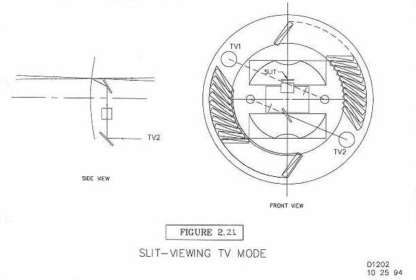
2.10.4 Slit-viewing TV
A direct slit-viewing TV would simplify object acquisition greatly for single object
observers. We believe that it will be possible to convert one of the offset-guiding TVs to a
slit-viewing TV by the insertion of two mirrors, as shown schematically in Figure 2.21.
The beam would be reflected upwards off the slit at an angle toward the center of the focal
plane, and then directed to a second mirror tilted toward one of the TVs. The detailed
optics for this system are not yet designed. It is probable that one of the mirrors will have
to provide power in order for the system to be parfocal with the offset-guiding TVs.
2.10.5 Thermal
The TV thermal properties are summarized under the mechanical discussion in Chapter 5. Briefly, the TVs will be enclosed in thermally insulated enclosures and isolated
from the main focal plane area by quartz windows. Cooling systems will carry the heat
away where it can be dumped into the main DEIMOS cooling system.
Lines mm-1 Blaze Ĺ mm-1 Usable Range
Size Available 1200 6000 Ĺ 21.7 4160- 9979 Ĺ
8 x 12 Yes 830 6000 Ĺ 31.5 4160- 9979 Ĺ
6 x 8 No 600 7500 Ĺ 43.2 5197-11000 Ĺ
6 x 8 Yes