1.0 Overview
Slider4 flexure test setup on the rotator in the Optical Lab and results are documented below. The existing design of Slider4 was tested with various clamps and temporary modifications. The results of these tests were then incorporated into design changes in Sliders 3, 4 and 5. From May 31, 2001 through June 14, 2001, eighteen separate tests were run using the optics lab testbench environment. The results of these tests can be found by reviewing the charts referenced below.
2.0 Reference Material:
Rotation Angle Conversion Document:
This document references the rotation angles used during flexure testing.
DEIMOS software command rotates to position angles per nomenclature referenced
under ROTATVAL. DEIMOS hardware tests use position angle nomenclature referenced
under Yellow Labels.
DEIMOS Rotation
conversion.pdf
Slider4 Gauge Placement Drawing:
Assembly drawing shows the placement of the Mahr Gauges and Dial
Indicator Gauges used during the flexure test.
grating_test_plate_slider4.pdf
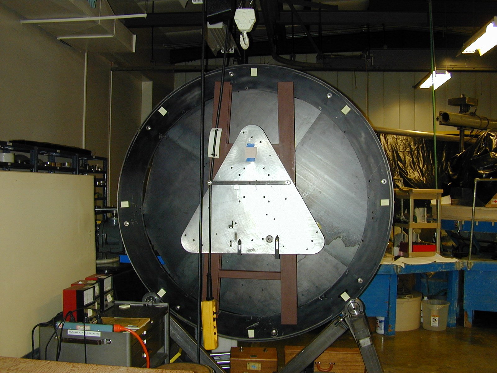
Testbench Image:
An image of the test bench used during
flexure testing.
optic_testbench.jpg
Charts of Flexure Test Results:
Excel spreadsheet charts reflect a series of tests performed to measure
flexure. The graph lines on the charts are Excel trend lines
slider4_charts.pdf
slider4_charts.xls