The Tip-Tilt Camera
|
This is an introduction
to the Santa Barbara Instrument Group (SBIG) camera and
discusses the concepts of digital sensors and
tip-tilt correction of astronomical images using adaptive optics (AO).
|
Digital Cameras
 Light waves consist of "packets" called
photons which are focused by the telescope into the camera.
A digital camera records this image as a
rectangular array of numbers.
The array, or charge-coupled
device (CCD), is a detector composed of a grid of tiny sensors called pixels which are each able to sense photons
at an efficiency of nearly 100 percent. This is far better than the eye or
photographic film. In addition, CCDs have a linear response and a large
sensitivity range. That is, the signal produced is proportional to the number
of photons detected. Furthermore, the CCD is able to simultaneously distinguish very
bright and very dim objects.
Light waves consist of "packets" called
photons which are focused by the telescope into the camera.
A digital camera records this image as a
rectangular array of numbers.
The array, or charge-coupled
device (CCD), is a detector composed of a grid of tiny sensors called pixels which are each able to sense photons
at an efficiency of nearly 100 percent. This is far better than the eye or
photographic film. In addition, CCDs have a linear response and a large
sensitivity range. That is, the signal produced is proportional to the number
of photons detected. Furthermore, the CCD is able to simultaneously distinguish very
bright and very dim objects.
A CCD works in the following manner. Photons from the observed source
strike the detector and excite electrons. The detector then collects these electrons and
records a signal. The number of electrons collected in each part of the detector
corresponds to the intensity of the image at that location.
Tip-Tilt Correction
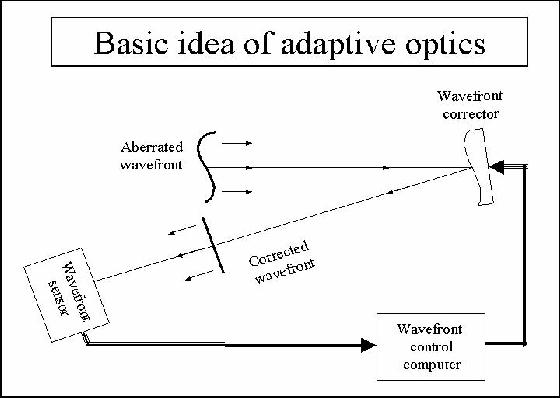
An AO system corrects for the distortion of images caused by turbulence in the
atmosphere. There are three parts to an AO system:
- Wavefront sensor
- Wavefront corrector (in our case, a mirror that tips and tilts)
- Wavefront control computer
The wavefront sensor measures the distortions in the wavefronts coming from a
bright guide star near the target object.
In our system this is done by rapidly taking pictures of a 7th magnitude or brighter star with a digital camera.
This is done many times per second.
These images are read out by the control computer, which finds the center of the star in each
and finds out how many pixels it has moved since the last picture.
Since the computer now knows how far the star has moved, it sends a signal for
the tip-tilt mirror to
move slightly in the opposite direction in order to move the star back.
Actually, in most AO systems
the mirror is placed
in front of the wavefront sensor, creating a feedback loop.
In this configuration each step can be smaller because it is only an
incremental improvement
on the last correction. This is called a closed-loop system,
and the SBIG tip-tilt camera operates this way.
The wavefront corrections need to be done in a
small fraction of a second due to the rapid changes in the Earth's atmosphere.
The track time is how long the wavefront-sensor camera exposes
for each picture.
It can be as short as 0.001 second for the SBIG system.
It then takes some time for the computer to read in the picture, find
the center of the star, and send a correction to the mirror.
The aggressiveness is how much the tip-tilt
mirror moves during each corrective step. Too low an agressiveness will make the the mirror move very
little and almost no correction will be made. Too high an aggressiveness
will cause the mirror to move too much and the system will oscillate wildly.
The
bandwidth refers to the frequency that the system is able to perform both the measurement
and corrective steps.
A higher bandwidth results in better images. The SBIG camera can achieve bandwidths as high as 50 times
per second.
Scientific Observations
 The SBIG tip-tilt system actually has two digital cameras. The first
is used to follow the motion of the guide star and allow AO correction with the tip-tilt mirror.
The second is used to
take the AO-corrected picture of the scientific target. Both are controlled by the same computer.
The SBIG tip-tilt system actually has two digital cameras. The first
is used to follow the motion of the guide star and allow AO correction with the tip-tilt mirror.
The second is used to
take the AO-corrected picture of the scientific target. Both are controlled by the same computer.
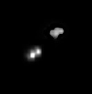
On the right are two images of the same binary star taken with our system. Binaries are two stars which orbit about each other. Without AO
it is very hard to be sure that there are two stars (upper right), but with AO correction
much of this blurriness goes away, and the two stars are easily distinguishable (lower left). We can measure, in arcseconds, the
separation of the two stars. If we know how far away the binary
is, we can use a little geometry to determine what the physical separation of the two components are.
Go home.
Home |
Telescope |
Manual |
Experiments |
Glossary |
People |
Visits/Publications
|