|
Contents:
 Home Home
Telescope
|
Astronomical Adaptive Optics Demonstrator
Instruction Manual
|
This is a complete manual for the setup and use of the Astronomical Adaptive Optics (AO) Demonstrator. Instructions for
the Meade 0.25 meter telescope are given. Details for the operation of the Santa Barbara Instrument Group (SBIG) tip-tilt AO camera
are presented. It is possible that your institution will have a suitable replacement telescope, and in that case only the AO camera will be shipped to
you.
Two of the most important prerequisites for making the demonstrator work are achieving good polar alignment and excellent focus with
the telescope. Operating the AO camera may seem difficult at first, but we have learned many tricks for getting good performance, and we
outline them here. You shouldn't expect dramatic results with the tip-tilt system, only a modest improvement in full-width at half maximum (FWHM) of
about 25 to 50 percent. However, this is still a significant improvement, and will make it possible to resolve binary stars only
otherwise observable from excellent mountain-top sites.
|
 |
PACKING LIST
- One Meade LX200 0.25 meter, f/10 Schmidt-Cassegrain telescope.
- One Santa Barbara Instrument Group ST-7E charge-coupled-device (CCD) digital camera with an A0-7 tip-tilt module.
- One laptop computer pre-loaded with CCDOPS, the software for operating the camera.
Contents
The Telescope
GENERAL WARNINGS
- Serious damage can be caused to the drive motors if they are left engaged and are jarred
in any way. Before storing, crating, or juggling the telescope, unlock the right
ascension and declination drive motors.
The RA (right ascension) lock knob is located on the base of the fork
adjacent to the RA slow motion control knob. The Dec (declination) lock is the black knob
located on the arm of the fork, adjacent to the dec slow motion control knob.
- To prevent damage to the primary mirror a bolt has been installed to hold it in place.
Before attempting to adjust the focus, REMOVE THE RED BOLT located beside the focuser knob.
A rubber stopper has been provided to fill the hole and prevent dust
from entering the telescope.
- Do not over tighten screws, locks and bolts. It's not a fire hose; only a firm feel
should be required.
- Finally, please do not look at the Sun. It can damage both your eyes and the optics of
the telescope.
|
THE FIELD
TRIPOD
- Assembling a Collapsed Tripod
- Caution: If the tripod does not seem to extend or collapse easily,
do not force it. Forcing the tripod may damage the extension strut system.
Stand the tripod vertically
with its feet down and still fully collapsed. Open the tripod by
tilting all it's weight onto one leg and pull gently on the
other two until the tripod is fully extended.
- Thread in the 6 lock-knobs into the holes on the legs near the feet of the tripod.
(two per leg).
Caution: Over tightening of the lock-knobs could strip the threads or
damage the tripod. Only a "firm feel" tightening is required.
|
 |
- Replace the spread bar (which has been
removed for shipping) by first removing the rod that is threaded
through the tripod head. Remove the "C" clip attached to the rod
via the plastic bag.
- Slide the threaded rod through the
spread bar (note the spread bar's "flat-side-up" orientation)
and place it back to the tripod head.
- Place the "C" clip retainer into the
slot in the thread rod.
- Position the three arms of the spread bar so that they align with the three legs
of the tripod and maneuver the rod until it extends above the top of the tripod head.
|
- Collapsing an Expanded Tripod for Storage
- Remove the telescope and equatorial
wedge.
- Off set the spread bar so that each of
its arms lie between the adjacent leg.
- At the base of the tripod is a 3-vaned extension strut system. Support the head of
the tripod and pull directly up on the center hub of the extension struts, collapsing the
tripod.
|
Contents
ATTACHING THE EQUATORIAL WEDGE TO THE TRIPOD
- Along the outer rim of the tripod head
are two nylon set screws; remove them.
- Attach the tangent arm to the rim (as
pictured) using the two supplied 8-32 X 1/2" socket cap screws.
- Place the equatorial wedge on top of the
tripod so that the threaded rod passes through the center of the
hole on the wedge floor.
- Make sure that the pin extruding from the bottom of the wedge, (called the azimuth thrust bar
pin) is positioned in the slot on the tangent arm.
|
 |
- Screw on the manual hand knob onto the
threaded end protruding from the floor of the wedge.
- Place the compass into the hand knob.
- Slide the three 5/16-18 X 1-1/4 button
head screws through the clearance slots on the wedge floor and
thread them to attach the wedge floor to the tripod head.
- Set the tilt plate to your latitude, by loosening the tilt angle adjustment screws with
the Allen wrench provided. Align the vernier pointer with your latitude and retighten
adjustment screws. If you do not know your latitude, enter your address
here.
|
|
Note: If your latitude is greater than 55 degrees, move the locking bolts
(tilt angle adjustment screws) on the tilt plate to the lower holes to
provide greater access.
Contents |
MOUNTING THE TELESCOPE ON THE EQUATORIAL WEDGE
- Note: Mounting or moving the telescope requires two people to properly support it.
Please get a friend to help.
- Make sure that the drive motor locks are
undone to prevent damage to the gears and encoders. It may be
required to SLIGHTLY engage the dec lock to prevent the telescope
tube from swinging.
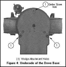
- On the underside of the base of the telescope are three holes for screwing it down
to the tilt plate. Thread one of the three mounting socket screws into the center most
of the three holes and tightening only about 3 full turns.
|
 |
- Check that the tilt angle adjustment
screws on the equatorial wedge are firmly tightened.
- Lifting from the fork arms with the power
panel towards you, carefully hoist the telescope on the wedge and
slid the socket screw into the slot at the top of the wedge.
- Insert the two remaining screws into the underside of the drive base. Tighten
down all 3 screws to a "firm feel." Extreme force is not necessary.
Contents
|
MOUNTING THE VIEWFINDER
- Mounting the Viewfinder.
- Slide the viewfinder into its bracket and
lightly tighten the 6 alignment screws.
- Slide the viewfinder bracket into its mating base on the telescope and
tighten the two thumbscrews.
- Focusing the Viewfinder
Note: The viewfinder comes pre-focused. However, if
needed:
- Loosen the focus lock ring.
- While Looking at a star, rotate the Dew Shield until the star is in focus.
Caution: if the dew shield is rotated counterclockwise to far, it will fall off. Only a
few turns should be required to refocus the viewfinder.
- Once focused, retighten the focus lock ring.
- Aligning the Viewfinder.
- Attach the 26mm eyepiece (as described below)
to the telescope.
- Locate and center some easy to find object in
the main telescope, make sure that it is at least 200 yards away.
- Adjust the 6 alignment screws on the viewfinder's bracket until the object is
also precisely centered with the viewfinder's crosshairs.
Contents
CONFIGURING THE POWER PANEL
Note: Make sure that the power panel is off before performing any of the following.
- Set the N/S switch. North for north of the
equator and South for south of the equator.
- Connect the declination (DEC) motor via the
8-pin cable from the "dec motor" jack in the right arm fork to the "dec
motor" jack on the power panel display.
- Plug the keypad hand controller to the keypad
connector by the standard 4-pin telephone-like cable.
- Power up the telescope by plugging in a standard 12-18V AC adaptor into the "Power
(18v DC)" jack connector.
Contents
ENTERING BASIC INFORMATION
- Location of the Observing Site
- Locate the longitude and latitude of your observing site to an accuracy of
about 1 or 2 arc minutes. You can do this by a number of ways -be it an atlas,
topographical map or you could just look here.
- Turn telescope on. (The switch is
located on the power panel.) After a few seconds, the display
will look like display 1. You can move up and down the menus
with the arrow keys provided on the bottom row of the keypad.
- Select the telescope entry by pressing
ENTER. You should now see display 2.
- Select the site entry by pressing ENTER, leading to display 3.
|
 |
- Display 3 is a list of possible site
entries. Use the arrow keys to move to the first unoccupied
entry. This is probably the first one. Press and hold the ENTER
key until it beeps. You should now see display 4 with the first
letter flashing.
- If you wish, rename the site entry from
AAA. You may move through the title with the east and west keys
and cycle through the alphabet with the up and down arrows. When
you're finished, press ENTER taking you to display 5.
- Using the number keys, enter your
latitude in degrees and minutes. Mistakes can be corrected by
again moving the cursor with the east and west keys. A negative
latitude can be entered by highlighting the "+" and hitting the
"NEXT" key. (It's in the lower right hand corner.) When the
latitude is correct, press ENTER, showing something like display
6.
- Enter your longitude just as above.
When you're completed press ENTER, returning you to display 3.
- Press MODE twice to return you to display 1.
|
- Local Time and Date
- The local time should be set as accurately as possible, so choose your source
wisely. (One possible source is here.)
- Turn on the telescope and wait for the
handset to show display 1. (If for some reason it does not,
press the MODE key until it does.)
- Press the MODE key twice so that the
display will look something like display 7.
- Press and hold the ENTER key until the
keypad beeps showing display 8.
- Using the number keys, enter your current local time within an accuracy of five
seconds. Please remember to use the 24-hour (military time) format. Mistakes
can be corrected by again moving the cursor with the east and west keys.
|
 |
- Press ENTER when the time is correct,
leading to display 9.
- Enter (using the number keys) the number of hours you are off from Greenwich
Mean Time. US time zone shifts are listed in the table below. If you are using the
LX200 east of Greenwich you must position the cursor backwards (by using the W key)
on the + (plus) sign and change it to a - (minus) by pressing the NEXT key. Then
enter the number of hours normally. When you're completed, press ENTER.
|
U.S.A. Time Zones
|
| Region |
Hawaii |
Pacific |
Mountain |
Central |
Eastern |
| Standard Time |
+10 Hours |
+8 Hours |
+7 Hours |
+6 Hours |
+5 Hours |
| Daylight Savings Time |
+9 Hours |
+7 Hours |
+6 Hours |
+5 Hours |
+4 Hours |
- You should now see display 10. Press
and hold the ENTER key until the keypad beeps. The cursor should
now appear over first digit of the date
- Now enter the current date in the
MM/DD/YY format. Any errors can be corrected using the E and W
keys. Press ENTER when finished.
- The hand controller should now display "Updating planetary data." You are now
finished with entering the vital information.
|
Contents
SLEWING THE TELESCOPE
To slew the telescope, i.e. to point the telescope to
a different part of the sky, is a simple matter of using the N, S, E, W buttons
on the keypad (N will move the telescope north, S - south, etc).
To select different drive speeds, press one of the four buttons on the
left hand side of the keypad. The current speed selected will be illuminated.
The speeds are labeled in descending order by the words: SLEW, FIND,
CENTER, and GUIDE (SLEW is the fastest, GUIDE is the slowest).
Contents
USING THE GOTO OPTION
-
To make the telescope point at a
specific location in the sky, press MODE until the current RA and DEC of the telescope is show.
-
Press the GOTO button so that first digit is
flashing.
-
Using the numbers on the keypad and the E and W buttons
to skip and correct, input the desired right ascension. When completed,
press ENTER.
-
Using the numbers on the keypad, input the desired
declination. To select a negative/positive declination, press E
until the sign is highlighted and then press PREV/NEXT. When
finished. press ENTER.
-
The telescope will now slew to the desired
location. However, it will not slew to a object below the
horizon.
Note: The telescope is unaware of the length and
placement of the objects attached to it. Therefore, it is quite
possible that in attempting to GOTO to a given position, any equipment
attached -such as an adaptive optics camera- will be knocked
into the fork of the telescope. This is extremely bad for both the
telescope and camera! When in doubt, just slew it yourself.
Contents
BASIC POLAR ALIGNMENT
- Set up and shift the telescopes tripod so that the telescope's fork arm points
due north. The compass set in the equatorial wedge base might prove useful in this situation or if the star Polaris
is visible, sight it along the tube of the telescope. (A description for finding Polaris
is here.)
Note: For this procedure, Polaris must be unobstructed and visible. If for some reason Polaris
cannot be view see you instruction manual for an alternate alignment procedure.
- Level the telescopes drive base with the bubble level set in the equatorial wedge's floor by
adjusting the height of the three tripod legs, making sure the bubble is in the center of the circle.
|
|
- Turn the power to the telescope on. (The switch
is located on the power panel on the drive base.)
- Select the following series of menu items: TELESCOPE, ALIGN, and POLAR. To maneuver the menus, use PREV and NEXT to scroll, ENTER to
select an item, and MODE to abort and proceed to the previous menu.
- Once the polar alignment sequence has
been selected, the hand pad should display "MOVE TO DEC 90. HA 0.
Press ENTER."
- In order to set "HA 0", you must first unlock the RA drive and then line up the following items: the hash mark on the drive base, the "00"
mark on the moveable hour angle wheel and the "Vernier scale" on the base of the fork arm. Relock the RA drive. When completed, the telescope
should be "upside down" with the viewfinder towards the ground (as shown.)
|
|
- Unlock the DEC motor and swing the telescope so
that the telescopes declination reads 90 and the tube of the telescope
points at Polaris. Relock the Dec motor.
- Go back to the keypad controller and press
"ENTER", this will move the telescope so the viewfinder is accessible
and (hopefully) Polaris is within its view.
- Using only the azimuth and fine latitude
control knobs, center Polaris.
Note: Due to a large amount of hysteresis in the control knobs, centering Polaris is not an easy task. It may be useful to iteratively
repeat this polar alignment procedure, there by each time improving the telescope's accuracy. A technique that might make this go faster is to
not completely center Polaris in the telescope's view, but only go half the distance, there by decreasing the risk of "overshooting" the
center.
Also, at this point it may be a good idea to double check the declination setting circle, located at the top of the fork. When
Polaris is centered, the declination should read 89.2 degrees. To adjust the circle, simply remove the knurled central hub of the Declination
setting circle and slightly loosen the two bolts located under the knob. When finished, retighten the bolts and replace the knurled hub.
- Once Polaris is centered, (or is close enough)
Press ENTER. The telescope will now slew to a bright star that is high
in the sky. Center the star by slewing the telescope with the N, S, E,
and W keys. When completed Press ENTER. .
Contents
ITERATIVE POLAR ALIGNMENT
|
As experience with this telescope has increased,
it has been discovered that often the tracking and pointing
accuracy of the telescope after a single polar alignment is hardly sufficient. Therefore, a iterative alignment procedure has been
developed.
- Perform the polar alignment procedure
described above.
- Repeat the polar alignment procedure with the following
exceptions:
- When presented with the "Move to Dec 90 HA 0" display,
IGNORE this command and DO NOT PRESS ENTER! Pressing enter will point
the telescope to the ground and destroy any previous alignment.
Instead, press the GOTO button which will then slew the telescope to
Polaris.
- When "centering" Polaris do not actually center Polaris. Instead, only halve
the distance between Polaris and the center of the view. On the
next iteration, again only halve the distance, etc.
- Repeat until Polaris is centered in the field without the need
for any adjustments.
This method efficiently guarantees that the
telescope is actually polar aligned by repeatedly slewing to another
star, centering it and then returning to Polaris. The pointing
accuracy and tracking is improved tremendously, and while it is time
consuming (it takes about an hour to do properly), this is recovered in less time spent
searching for the object of interest.
Contents
HIGH PRECISION ALIGNMENT
|
When needing to point to a specific and
not easily recognized location in the sky, it is
recommended that you use the HI PRECISION alignment option.
When the telescope is pointing at different locations in the sky, the weight on the drive motors will
be different and this dramatically effects the pointing accuracy. To
correct these inaccuracies, the telescope will reorient itself in
the sky by first locating a bright star near the
object of interest.
To Turn It On:
-
From the TELESCOPE menu, select the
ninth option "hi precision" by clicking enter. This
should capitalize the text so that it will now read HI
PRECISION, indicating that it is now on.
To Turn It Off:
- Reselect HI PRECISION from the TELESCOPE menu so that it
will now read "hi precision".
How to Use It:
Once
HI PRECISION is selected, it will be activated whenever a GOTO
is used. See USING THE GOTO
OPTION above.
- Enter the desired RA and DEC for
the desired object and press GOTO.
- The telescope will then select
three bright stars near to the desired object and will ask
you to center one. for example "Please center star 103
then press GOTO". The number indicated is the listing
in the telescopes star catalog, beginning on page 43 of the
LX200's instruction manual.
- If for some reason the first star
is unacceptable, select the next star by using the PREV/NEXT
keys at the bottom of the keypad.
- Once the star is centered, press GOTO and the telescope
will slew to the desired object.
Contents
| |
Figures 1-8 displayed above are copyright � 1998 Meade Instruments Corporation.
|
|
The Tip-Tilt AO Camera
INSTALLING THE CCDOPS SOFTWARE UNDER WINDOWS
- The software for running the AO camera is CCDOPS, provided by SBIG.
To install, either insert the
first CCDOPS disk into your floppy drive or download the
latest version of CCDOPS directly from SBIG.
- Double click on
SETUP.EXE from you floppy drive or on the installation file downloaded and follow the directions presented by the installer.
Contents
CONFIGURING CCDOPS FOR USE WITH THE AO DEMONSTRATOR
- Start up CCDOPS.
- From the MISC menu, select TELESCOPE SETUP...
- Click on CALCULATE from the TELESCOPE SETUP
dialogue box.
- Select ST-7 from the CAMERA pull-down menu.
- Input the proper APERTURE DIAMETER,
OBSTRUCTION DIAMETER and F/RATIO for your telescope. Note that the
diameter measurements are in inches. For the f/10 10" included here,
these numbers are: 10.00, 3.7, and 10.00.
- Click CALCULATE followed by DONE to close the
FOV CALCULATOR.
- Click OK to close the TELESCOPE SETUP menu.
Contents
UNPACKING THE AO CAMERA
|
- To protect the AO mirror, a piece of cardboard
and lens cloth has been inserted in the AO module for shipping. To
remove them, unscrew and remove the four long screws (as marked in
Figure 1) that join the mirror assembly to the camera and the attachment
elbow.
- Carefully remove the cardboard and lens cloth.
|
|
- Reassemble the two halves of the AO module,
making sure that the cable exits on the right side of the module, (as
shown in Figure 1.)
- Attach the cable linking the AO module to the camera.
Contents
ESTABLISHING THE COMPUTER-CAMERA LINK
- In order for CCDOPS to
be able to communicate with the camera and AO system a few things must
first be configured. First, connect the camera module to a computer with
CCDOPS installed via the printer cable provided.
|
- Fire up both the computer and camera. The
camera powers up only by plugging in the AC power adapter. It's on when
you hear the fan.
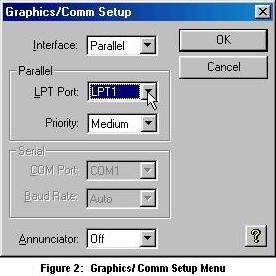
- To tell CCDOPS where the camera is located,
open the program and select GRAPHICS/COMM SETUP... from the misc menu.
- From within that menu,
set INTERFACE to "parallel" and LPT PORT to the parallel port
being used.
|
|
|
(Most likely that port will be
LPT1. Note: If you notice horizontal streaks in your images, you might want
to change the PRIORITY to medium or higher.)
- When finished, click OK.
- Select ESTABLISH COM
LINK from the Camera menu to finally initialize the link.
Contents
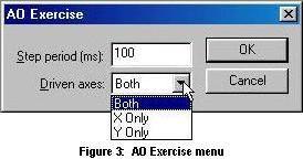
TESTING THE AO MIRROR WITH THE EXCERCISE FUNCTION
- It's a good idea to
test the AO mirror's movement and make sure nothing particularly bad
happened to it in transit. The CCDOPS program offers an excellent
feature for doing just that. From the AO menu select
EXERCISE...
|
|
- The exercise option
will move the mirror to the limits of the axis selected over the desired
period of time. To test the mirror, simply observe some distant light in
the mirror and activate the EXERCISE option. If the mirror moves, it's working fine.
|
Contents
FOCUSING THE TELESCOPE WITH THE AO CAMERA
- It's a good idea to first obtain a rough focus
with the telescope before trying to focus with the AO Camera. Only a
rough focus is needed, it'll change once the camera is attached anyway.
To do so, point the telescope at a rather bright star. The out of focus
image should appear as a "donut" of light and get smaller as the focus
is improved.
- Attach the camera to the telescope and then
power it up. Attaching the camera to the telescope is a simple matter of
screwing it on, but be careful not to cross-thread the attachment ring.
A helpful technique for lining them up correctly is to spin
the attachment ring backwards until you feel the treads fall into place. The telescope
attachment ring (as shown in Figure 1) should fit most "Schmidt-Cassegrain" telescopes.
It is advisable to orientate the camera so that the flat portion
is facing down and is parallel to the DEC axis of rotation.
This ensure that the top of the image is north in
the field.
- Start CCDOPS and, if it is not done automatically, select ESTABLISH COM LINK from
the Camera menu. If you see the error, "you need to set a parallel port...",then do so. If
you get stuck, see ESTABLISHING THE COMPUTER-CAMERA LINK above.
- Select the SETUP command from the Camera menu
to initialize the basic operational parameters of the camera (see Figure
4).
|
- Set the temperature regulation parameter
to on. The set point option will set the number of degrees below
ambient temperature the unit will be cooled to, -20�C should be
good.
- Configure the Active CCD to "imaging" and the resolution mode to "High." (See below for
a further description of the resolution modes.)
The other options with in this menu are rather important and are worth exploring.
Consult the help menu by clicking on the question mark in the lower right hand corner
for more information.
|
|
|
- Select the FOCUS command from the Camera menu.
What it does is automatically exposes and displays new images from the
CCD, thereby allowing you to be able to see the adjustments being made.
- To dramatically speed up the download time of each image, select "Planet" from the "frame
size" field. The planet option reduces the refreshed portion from the full CCD to an
area selected by the user, which speeds things up immensely.
|
|
- Input an exposure time and for the rather
bright object being observed, a .25 second exposure should be plenty
(the shortest time available is .11 seconds.) A longer exposure time of
course allows fainter objects to be seen but the trade off is a longer
time spent focusing and less time observing. When selected, click OK.
- The camera should now expose the entire CCD and
then allow you to select the portion that will be refreshed. To do so,
simply click and drag the box to the desired star (To resize the box,
simply grab one of its corners.) It is recommended to select the
brightest star in the field first, then later move on to a dimmer one.
Click the "resume" button from the focus window, when finished.
- Begin adjusting the focus of the telescope. An eighth to a quarter of a turn
progression is recommended. Try to wait at least two images between turns, just to let things settle.
Progress means the donut/star is getting smaller until it reaches a small circle.
Each time an image is displayed, the contrast window will read out the number of counts of the brightest
pixel viewed. (The number of counts is basically the amount of light falling on the pixel.) As the focus
improves, more light is concentrated in a smaller area so the number of counts should increase. However,
when the value reaches about 65,000 the CCD is saturated and you must now move to a fainter star
in the field, (5th of 6th magnitude). Exit and restart the FOCUS command to select a fainter star.
The sharpest focus will be when you get the highest average number of counts.
Note: With most Schmidt-Cassegrain telescopes, the focus knob actually moves the primary
mirror and because of that it may be difficult to return to focus when overshot. Therefore it
may be a good idea to approach the focus from only one direction, (i.e. turning the knob only
clockwise) instead of trying to backtrack. If you do miss it, simply back up and try it
again.
Contents
TAKING NON-AO (UNGUIDED) EXPOSURES
|
- To take an unguided exposure, simply
select GRAB from the camera menu, displaying Figure 7.
- Set the desired exposure time and whether or not you wish a dark frame to be taken.
(ALSO means that both an image will be taken as well as a dark frame and then automatically subtracted. NONE/ONLY are
rather self-explanatory.) To find out what a dark frame is and why it's needed, see the
Appendix.
|
|
|
Note: Images taken with the AO
camera and the LX200 telescope described above are flipped E-W when viewed on the computer screen.
A few other points of note: The image size option
sets the way in which the pixels are binned. (Binned meaning that an
area of pixels will be average together to form a smaller, but more
intense, image.) The obvious draw back of binning is that it creates a
less detailed image. However, it does in effect increase the intensity
of the image by concentrating the light into a smaller area. Full sized
images are un-binned, medium are binned 2x2 and low are binned 4x4. Also,
to take an image with the other CCD, select "switch CCDs" from the
camera menu. You will always know what CCD is being used by the status
bar in the lower right hand corner of the CCDOPS screen.
Contents
CALIBRATING THE AO SYSTEM
- Once the AO system is attached and focused, it needs to be calibrated: Select CALIBRATE
from the AO menu.
The shortest exposure time allowed is .11 seconds and that should be enough
for the system to calibrate, assuming the telescope is still pointed at the bright object
used for focus. Otherwise, select the best exposure time for the object being observed
and click OK.
Note: If the bright star you are using has any equally bright neighbors, you might consider
locating another target or else the calibrate function might get confused.
- The AO system will now move the mirror in all for directions and record the correction
speeds. The +X and -X times should be about the same, as should the �Y numbers and
all of them should be with in a factor of two. If this is so, you AO system should be properly
calibrated.
Contents
SETTING UP A GUIDE STAR
The AO camera has two CCDs, one for taking
the desired exposures and another for tracking the guide star so that
the AO system will function. Centering the guide star on the
tracking CCD is not an easy task. The relation between the two CCDs
is that the tracking CCD is directly above the imaging CCD (see Figure 8).
The appendix entry on CCD
Spacing has the exact dimensions between the two.
-
The first and most important step is to obtain
a solid polar alignment with the telescope, so that the tracking is
phenomenal. If the tracking is poor, this may be next to
impossible.
-
Make sure the camera is rotated properly so
that the top of the image is aligned with the top of the field of view, i.e. so
that a slew of north will shift stars to the bottom of the image.
-
Start a FOCUS option what a short exposure
time and a full frame size so that any adjustments to the location of
the telescope can be see.
-
Center the chosen guide star on the imaging CCD. Slew
the telescope south so that the guide star goes to the top of the image
and just off the frame.
-
From the CAMERA menu select SWITCH CCDs to use the tracking
CCD.
-
Again, start a FOCUS option what a short exposure time and a
full frame size.
-
Slowly continue slewing south until the guide star is near the center
of the tracking CCD.
-
Again select SWITCH CCDs to return to using the imaging CCD.
Contents
ROTATING THE CAMERA
Unfortunately, it is often necessary to rotate the camera so
that both the guide star and the object of interest can be seen by the two
cameras. This introduces an entirely new set of challenges in driving
the telescope because the top of the image will no longer be north of the
field. It's really hard! When you need to rotate the camera remember
these points:
-
Center the guide star first on the imaging CCD with the
FOCUS option on.
-
This is a trick that helps keep the directions
strait: Keep the hand paddle in the same orientation as the
camera. That is, if the camera is rotated 45� clockwise, rotate the
hand paddle 45�. This way, you know that to drive the star up, you need
equal amounts of south and east.
-
Make small moves and always keep the guide star in the
frame. Rotate the camera a little bit, then center the guide
star. If you rotate too much, don't panic, just rotate the camera
back until the star is in view.
-
If you get really lost, return the camera to the default orientation and re-center
the guide star.
Note: The camera rotates at a point between the two
CCDs.
Contents
TAKING AO (SELF-GUIDED) EXPOSURES
- Before attempting to activate the AO system
with the self-guide function, it's a good idea to get a feel for how the
star field looks (either by repeated observations or a
finder chart) and note which way the camera will be rotated in
order to properly align the guide star.
- As described above,
center the guide star.
- When you have a guide star, it's a good
idea to switch back over to the imaging CCD and take a brief exposure
just to double-check that you still have the target and the focus is still
sharp. Adjust as necessary.
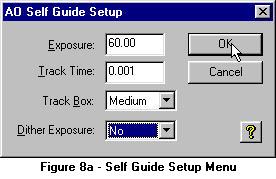
- If everything looks good, select SELF GUIDE
from the AO menu. The menu in Figure 8a will appear, allowing you to set the
exposure time to the desired value and other options. Dither will
perform a double exposure, one with the AO system on and another
slightly displaced with it off. The tracking box sets the area that will
be refreshed on the tracking CCD as well as the point where the guide
star will be centered. The smaller the tracking box, the better the
frame rate; however if it's too small, the star could wander of the
frame. Recommended starting parameters: a 60 second exposure with a
tracking time of 0.1 second, and a medium sized track box and without
dither.
- Once begun, the camera will take a short
tracking CCD exposure, display it and prompt you to select your guide
star by placing the tracking box around it. It need not be centered,
the AO system will center it on its own. Hit enter to begin the
tracking.
- Ultimately, The star will now be pulled to the center of the displayed tracking box and the guide star
will be contained only in four equally bright pixels. At least, this will be the case under ideal conditions. Once things
have settled down click START to begin taking the desired image. See the
appendix for a discussion about aggressiveness of the AO system.
Contents
SHUTTING DOWN FOR THE NIGHT
- Before powering down the AO camera, you should
do nice things to it like first allow it to come into equilibrium with the ambient
temperature. Therefore, before turning off the camera for the night,
select SHUTDOWN from the Camera Menu. This will slowly increase the
temperature of the camera until it reaches ambient as well as opening
the shutter and breaking the communications link.
- Wait about 30 seconds before unplugging the
camera.
- Pack up the camera. If you will be using it again, you will not need to replace the lens cloth and cardboard but
if you will be reshipping it, please do so.
Contents
APPENDIX
-
Aggressiveness
The aggressiveness is how much the mirror moves for each correction; the default value is 10. An
aggressiveness of 5 would move the mirror half as much. A value of 20 would move the mirror twice as much.
Try to select a value that will best suppress the wander (displayed here in units
of arcseconds) of the star displayed in the Guiding Dialogue. You can tell if the aggressiveness is too
high when the star begins to oscillate wildly. The most probable values will be between 5 and 15 but, as with
everything, play with it until an optimum is found. (The aggressiveness can be adjusted during guiding
by hitting the + and keys.)
CCD Arrangement and Plate Scale
One of the real tricks of actually taking a
self guided image, is finding the correct position and rotation for the
camera so that your bright guide star falls upon the tracking CCD while still
being able to view your scientific target in the imaging CCD. There is a fine
art to the centering and Figure 6 shows the size and positioning of the two CCDs
relative to the camera orientation shown. Note: The camera will rotate at a point
somewhere between the two CCDs.
However, knowing the distance between the CCDs is
only half the battle.
You must also know the distance on the sky between the guide star and
the scientific target. That is, you need to know the field of view (FOV) of the CCDs on the
sky. This scaling is a function of the focal length of the telescope. The
plate scale (S in units of
radians/unit length) is
S = 1 / f
The value of f
is the focal length of the telescope. It may be helpful to remember that the
focal ratio is just the ratio of the focal length to the telescope's
diameter. Once the plate scale is known, it's a simple matter to obtain the FOV
of the CCDs.
A correctly scaled version of Figure 9 for an f/10 telescope is contained here in PDF format.
The scale of the diagram is 1 cm=1 arcmin scale.
 CCD_dim.pdf CCD_dim.pdf
Dark
Frame
Like a solar cell, CCDs are able to transfer the energy
received from light into an electrons. A CCD counts the number of electrons received from every pixel on the detector.
However, sometimes a pixel will get enough heat energy to trigger an electron, and thus a spurious current is created
even when the shutter is closed. This is called a "dark current." To fix this, an exposure is taken of
of the same exposure length as the scientific observation, but with the shutter closed. It is subtracted from the original image.
|
Contents
Home |
Telescope |
Tip-Tilt Camera |
Experiments |
Glossary |
People |
Visits/Publications
|