


ESI CCD Electronics Manual
Wiring:
Interconnection Diagram for the ESI SDSU2 CCD Controller, EL-3273
The interconnection diagram for the ESI CCD Controller shows the overall flow of signals throughout the controller. At the very top and around the right-hand side and at the bottom is a wide line that represents the VME-style backplane. The controller contains a 6-slot, P1 type VME backplane into which the various SDSU2 controller cards are plugged into. Looking at the bus/backplane on the schematic, at the top are shown the SDSU2 Utility and Video boards. At the bottom is shown the Timing and Clock boards. Also connected to the bus are the eight lines from the power supplies (bottom left.) These lines represent the +5, +16, -16 and +38 volt supplies and their grounds. Note, the write-ups for the SDSU2 boards can be found that the following web page: http://mintaka.sdsu.edu/ccdlab/LabMain.html
EL-3193: Starting at the left, top of the page, the SDSU Utility board is shown connected to the UCO/Lick board EL-3193. A 64-pin cable connects the board to the SDSU Utility board. The main function of the Utility Support board is to route the various analog and digital I/O lines to the rest of the controller. EL-3270 gives a list of those signals and what functions are assigned to them.
P2
Looking at the EL-3193, P2 is the connection for a 64-pin ribbon cable that connects the Utility board ant the Utility Support board. Next to it is P14, a 24-pin ribbon cable connector which routes the CCD heater drive, temperature current source, analog switch enable, and the shutter open/close to the EL-3195 Power and Miscellaneous Signal board and receives the various shutter status lines.
P3-6, P10-13
At the right-hand side of the card are eight CCD connectors. These are each able of connecting to a single CCD amplifier chain. For ESI only one of these connectors is active; P6. In other applications others of these connectors might also be used. Also note that pin 7 of connector P13 is being used to control the cooling fans in the electronics locker in which the CCD controller is mounted. This is a modification to the normal use of the Utility Support board. The general-purpose nature of these boards has allowed us to wire-wrap a connection from the unused Dout14 signal of the SDSU Utility board to a pin on an unused connector, P13, to bring out the implementation specific FAN CONTROL line.
P15-19
At the bottom of the EL-3193 block are the five Clock Mux SMB connectors. In this configuration only the first of these connectors is used. This line allows the software on the SDSU2 Timing board to select and read back any of the clock waveforms that are being sent out the CCD dewar.
P9
Connector P9 is the connection to the EL-1198 Power Monitor board. These lines include the software enable of the +/-16V and +38V supply outputs and the analog switch enable request. Coming back from the Power Monitor board are the analog enable and external reset signals. The purpose of these signals is to keep the CCD chip safe from wrong voltages being applied. See the board description below for details.
P7
This connector brings in the +/-16V and +5V supply voltages onto the board. It is used on the board and is also passed to the EL-3194 61-pin Cable Interconnect card.
P1
This is the test connector that comes out the front of the card. It allows probing of any of the Utility board signals.
EL-3195: To the left of the Utility Support board is the EL-3195 Power and Miscellaneous Signal board. Its function is to send the power supply voltages to the dewar and provide a connector for the dewar shutter control and status lines.
P2
This is an external DB-16 connector that connects to the EL-1183 Shutter Controller. It passes the shutter open/close command and the shutter status signals. These signals include the left and right blade in and out signals and a SHUTTER_IS_OPEN signal.
P5
This is a 24-pin ribbon cable connector. It carries the command and status line from the Utility Support board. These include the shutter lines, the CCD heater and temperature lines, and the analog switch enable signal. The shutter lines go out on P2 and the dewar signals to P3 and P6.
P3, P6
These are 17-pin MS-type connectors. In most situations, only P3 is actually installed on the board. P6 would only be used if there were multiple dewar electronics boxes. These cables supply the +5V and +/-16V supplies to the dewar electronics box where they are filtered and wired to the Analog Switch board and the Preamplifier card. The other lines include the heater, temperature, and analog switch enable signals.
P1, P4
These are the white Molex power connectors. As above, P4 is only be used if there are multiple dewar electronics boxes. The connectors are wired directly to the +5V and +/-16V power supplies.
EL-1198: Beneath the Utility Support board is the EL-1198 Power Monitor board. Its function is, as explained above, to ensure that the power to the dewar is brought up and taken down in an orderly fashion. That is, the +/-16 volt supply comes on before the +38 volt supply. Again, this is just the power to the dewar not the rest of the CCD controller.
EL-3199: In the middle of the drawing is the EL-3199 Bias Cable Interconnect board. Its function is to take the 12 bias levels from the SDSU2 Video board and divide them up into two sets of six voltages. This allows the controller to be capable of running different system configurations. In the case of ESI, both output cables are fed to the 61-pin cable interconnection card.
EL-3198: In the lower right-hand corner of the drawing is the EL-3198 Clock Cable Interconnect board. Its function is similar to the Bias Cable Interconnect board above. It divides the 24 clock signals into two sets of 12, which are all that is required in most CCD configurations.
EL-3194: In the upper right-hand corner of the drawing is the EL-3194 Power and Miscellaneous Signal board. Its function is to receive all of the control signals for the CCD and combine them and send them out on the 61-pin umbilical cable to the dewar. In the center of the card is P1 the 61-pin connector that connects to the umbilical cable on the rear panel. This connector is soldered to the board and its mounting holes are used to attach the board to the back panel. At the top of the board are connectors P4 and P6. These connectors bring the SDSU2 Video lines onto the board where they are passed through to the dewar electronics box. At the bottom of the board is P7 that brings in the temperature, heater, power supply lines, and bias select control lines from the EL-3193 Utility Support board. Next to it is P2, which brings in the CCD clock signals. To the right is connector P5. This connector is for extra clock signals that are not used by the ESI CCD. On the left edge of the drawing is the 64-pin test connector. This test connector is provided for probing the signals on the board.
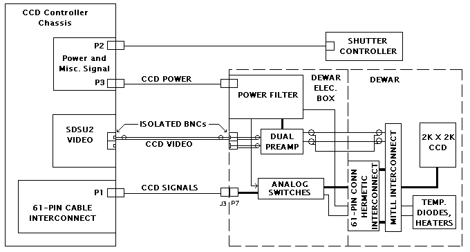
Dewar cabling simplified drawing
This drawing shows the interconnections between the CCD controller and the shutter controller, the CCD controller and the dewar electronics box, and the dewar electronics box and the dewar internal wiring. The box on the left-hand side of the page depicts the CCD controller. At the top of the box is a representation of the EL-3195 Power and Miscellaneous Signal board. This board is mounted to a panel and screwed to the back of the CCD controller. P2 shows the wiring to the EL-1183 Shutter Controller box. In ESI, the shutter controller box is mounted into electronics locker #2 along with the CCD controller. P3 is the power cable for the electronics box. It includes lines for the digital +5V supply and digital returns and the +/-16V analog supplies and analog returns. This cable also carries the analog switch enable signal and the temperature diode and heater lines.
Below the Power and Miscellaneous Signal block is the SDSU2 Video board block. The cable shown going out to the dewar is the video signal from the pre-amplifier. It connects to a BNC on the dewar electronics box and a BNC on the rear of the CCD Controller. The connector on the back of the CCD controller is a feed-through type BNC. Connected to it internally is a RG-174 cable with a BNC at the back of the controller and a SMA connector at the front of the controller that connects to the SDSU board. This is one of the two SMA connectors on the front edge of the video board.
The bottom block in the CCD controller represents the EL-3194 61-Pin Cable Interconnect board. This board holds the 61-pin connector to which the umbilical cable connects. This cable routes the clock and bias lines to the dewar electronics box.
Below the Shutter Controller block is a dash lined box that represents the CCD dewar. The left-hand side represents the dewar electronics box and the right side represents the dewar internal wiring. At the top of what is labeled 'Dewar Elec. Box' is the EL-3191 Power filter board. The dark line to the pre-amp board depicts the power supply lines. The lighter line to the left is the analog switch enable signal and the power supply lines for the analog switch board. The line leaving the block at the right-hand side depicts the temperature diode and heater resister lines.
Below the Power Filter board block is a block that represents the EL-1221 Dual Pre-amp. On the left-hand side of the block are the two video coaxes. Note: ESI is a single channel system and only uses one channel both on the input and the output of the pre-amp. On the right-hand side of the block are the connections through the wall of the dewar. We have uses 3 hermetic connector to isolate the video from chassis ground. Two of these connectors connect the video lines and the third one connects the ground. The heavy line coming into the top of the block depicts the power supply lines. The bottom box in the 'Dewar Elec. Box' block is the analog switch board. This board receives the umbilical cable from the CCD controller and provides analog switches that can isolate the signals that go to the CCD inside the dewar. On the left-hand side of the block the light line represents the power and analog switch enable signal coming in from the Power Filter board. Below that are the signals coming in from the umbilical cable. On the right-hand side of the block, the heavy line represents the clocks and voltages that are wired from the board to the 61-pin hermetic connector. These signals are each wired as twisted pairs with a ground wire. The light line represents optional extra temperature diode and heater lines. In ESI these signals are not used.
The right-hand side of the dewar block shows the wiring in the evacuated portion of the dewar. At the bottom of this block are the 61-pin hermetic connector and the EL-1227 connector board. These bring the signals in and out of the dewar. The 61-pin hermetic connector is soldered directly to the connector board. Mounted onto the connector board are two 32-pin header/connectors. The EL-1240 board plugs into these connectors as a 'daughter' board. The EL-1240 then connects to the actual CCD chip via a miniature DB-37 connector and a flex-circuit cable that is connected to the device. The video signal from the CCD connects via the flex-circuit but at the EL-1240 board it is sent out via a pc-mount SMB connector. These are wired to the three hermetic connector that bring the signal and its return out of the dewar. Also on the EL-1240 board is a four-pin connector that connects to the temperature diode and the heater resistor.
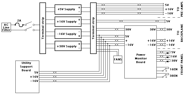
Chassis wiring simplified drawing
The EL-3275 Power Distribution schematic shows the wiring inside of the CCD controller. Starting at the upper left-hand corner, the AC power wiring shows that power enters the box via an AC plug/filter unit. This is used to help keep radiation both into and out of the box. The high line is wired to a 2 Amp slow blow fuse and then both the high and neutral lines are wired out to the front panel power switch. The switched lines then return to the back of the chassis and are wired to a terminal strip. This allows for cleaner wiring to the various power supplies. Note that all AC wiring is done using twisted pairs of white and black wire. The +5V, +16V, and -16V supplies each have fuses on the rear panel. The +38V supply has it's own fuse mounted on it's case. Notice that there is a twisted pair that routes the AC to the Power Monitor board. This is the wiring for the 115V AC monitoring.
The various DC power supplies are, by way of twisted pairs, wired to a set of terminal strips that face out the back of the chassis. To get to the strip remove the blank panel above the AC power cord. The grounds of each of the supplies are tied together with heavy straps at terminals 1 through 7 of the terminal strip. Also, notice that just below the +38V supply is an earth ground symbol that represents the grounding of the chassis. This is the single tie point for all of the various grounds. This is done to help eliminate any ground loops. The terminal strip connections are wired as follows:
(Terminals 1 through 7 are grounds tied together with straps)
Terminal Voltage Side 1 Side2 1 5V Return 5V Supply Pre-amps Utility Support board Power Monitor board 2 5V Return 5V Supply VME Backplane (2 wires) 3 +16V Return +16V Supply Pre-amps Fans 4 +16V Return +16V Supply Utility Support board Power Monitor board 5 -16V Return -16V Supply Pre-amps Utility Support board 6 -16V Return -16V Supply Utility Support board* Power Monitor board 7 +38V Return 38V Supply Power Monitor board 8 +38V 38V Supply Power Monitor board 9 -16V -16V Supply Pre-amps 10 -16V -16V Supply Power Monitor board Utility Support board 11 +16V +16V Supply Pre-amps Fans 12 +16V +16V Supply Utility Support board Power Monitor board 13 +5V 5V Supply Pre-amps 14 +5V 5V Supply VME Backplane (2 wires) 15 +5V 5V Supply Utility Support board Power Monitor board * This ground wire is twisted with the +5V wire that goes to the Utility Support board
To start with, notice the choke symbols associated with each set of wires leaving the power supplies. These are hand wound chokes consisting of ten co-windings of 18 AWG wire around a 1/2 " I.D. form. 18 AWG wire is used for all power supply wiring and each power supply wire is twisted with a ground wire. At the top of the page is shown the wiring to the EL-3195 Power and Miscellaneous Signal board. This is the power that is used in the dewar electronics box for the pre-amps and the analog switch boards. Directly below the pre-amp wiring and above the Power Monitor board is the +5V wiring to the VME backplane. The actual wiring consists of two 18 AWG twisted pairs to allow for the large currents on the backplane. The other voltages that go to the backplane are routed through the Power Monitor board. The +/-16V and +38V supplies are enabled according to a sequence controlled by this board. There is also a +5V supply connection to the Power Monitor board to run the logic on the board and for sensing the 5-volt level. Outputs from the Power Monitor board include the controlled +/-16V and 38V supplies to the VME backplane, the front panel indicators, and the front panel enable switches. The three indicator LEDs are yellow for +38V supply on, green for +/-16V supplies on, and red for +5V (and power) on. The manual enable switches are also wired from J3 on the Power Monitor board to the front panel. These, as their names imply, are used for local turn on or shut down of the +/-16V and 38V supplies. Shown in dashed lines are the optional local temperature readout and dimmers for the front panel LEDs. These are only installed into controllers that have access to the front panel.
The large box in the lower left-hand side of the drawing represents the Utility Support board. P7 of this board is wired to the +5V and +/-16V power supplies. The +5v supply is used for normal logic but the +/-16V supplies are used both for the analog sections of the Utility Support board and are also fed to the Utility board via the 64-pin interconnect cable to power the Utility board's onboard DACs. In the center of the page are the cooling fans that are connected to the +16 volt supply. These are wired to a 2-position terminal strip near the fans. The fans and terminal strip are accessible by turning the chassis over and removing the 2 screws that hold the panel onto the chassis.
The other wiring in the CCD controller is the interconnection between the Utility Support board and the Power Monitor board. These connections are made with 22 AWG wire from P9 of the Utility Support board and J2 of the Power Monitor board. In cases where the local temperature readout is installed, connections are wired from P8 of the Utility Support board to the Datel Digital Panel Meter.
AC Power Distribution, EL-3165
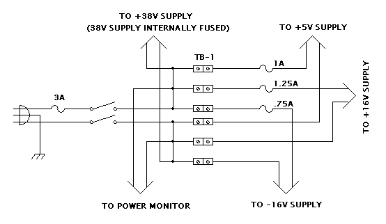
AC wiring simplified drawing
This diagram shows the details of the AC wiring within the controller. The AC enters the controller via a plug/line filter connector. The high and neutral lines are twisted together starting at the AC plug and run to the 3 amp fuse that is mounted on the lower back panel next to the plug. From there, the wires remain twisted and run up the left side (as viewed from the front) of the chassis to the AC power switch on the front of the chassis. Both sides of the power lines are switched and then run back to the rear of the chassis and terminate at the AC terminal strip that is located at the rear, center of the box. From the terminal strip a twisted pair runs to each of the DC power supplies and to the Power Monitor board. All AC wiring, with the exception of the lines to the Power Monitor board, is 18 AWG stranded wire. The wiring to the Power Monitor board is 22 AWG stranded wire.
CCD Controller Configuration , EL-3177
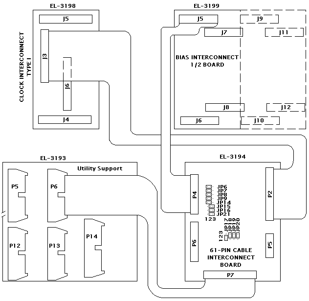
Simplified configuration drawing
This diagram shows the details of the signal routing between the various interconnect boards. Again, the system was designed to be general purpose enough to accommodate various types of CCDs and/or numbers of CCDs. As the diagram shows, the main interconnection point is the EL-3194 61-Pin Cable Interconnection board. Starting at the upper left-hand corner, the clocks from the SDSU2 Clock Generation are routed through the EL-3198 Clock Interconnect board. They leave the interconnect board at connector J3 as a 24-pin ribbon cable and connect to the 61-Pin Cable Interconnection board at P2. In a like manner, the bias levels from the SDSU2 Video board are routed through the EL-3199 Bias Interconnect board. They leave the interconnect board at connector J5 as a 14-pin ribbon cable and connect to the 61-Pin Cable Interconnection board at P4. The dashed outline on the Bias Cable Interconnect board indicates that card comes in either a four channel configuration or, as in this case, a sawed off (literally) two channel version. Both the clock and bias ribbon cables travel from the front of the chassis to the 61-Pin Cable Interconnection board via a shielded channel next to the VME card cage to reduce noise pick up. At the top left of the schematic is the EL-3197 Type II Clock Interconnect board. This board is not used or included in this configuration. At the bottom left-hand side of the drawing is the EL-3193 Utility Support board. The signals from this board go to the 61-Pin Cable Interconnection board via a 20-conductor ribbon cable. In the upper right-hand corner of the diagram is a jumper configuration table for the jumpers on the 61-Pin Cable Interconnection board. The jumpers are also pictorially shown on the 61-Pin Cable Interconnection board.

CCD Pre-amp simplified drawing
The pre-amp wiring is shown on schematic EL-3274. The wiring consists of the signal in, the amplified signal out, and the power wiring. The input and output wiring consists of two SMB connectors each. The input comes from the hermetic BNCs mounted on the dewar. The output wiring leaves the board via SMB connectors and connects to isolated BNCs on the exterior of the dewar electronics box. The +/-16V power for this board comes from the Power Filter board via a 4-pin Molex connector.
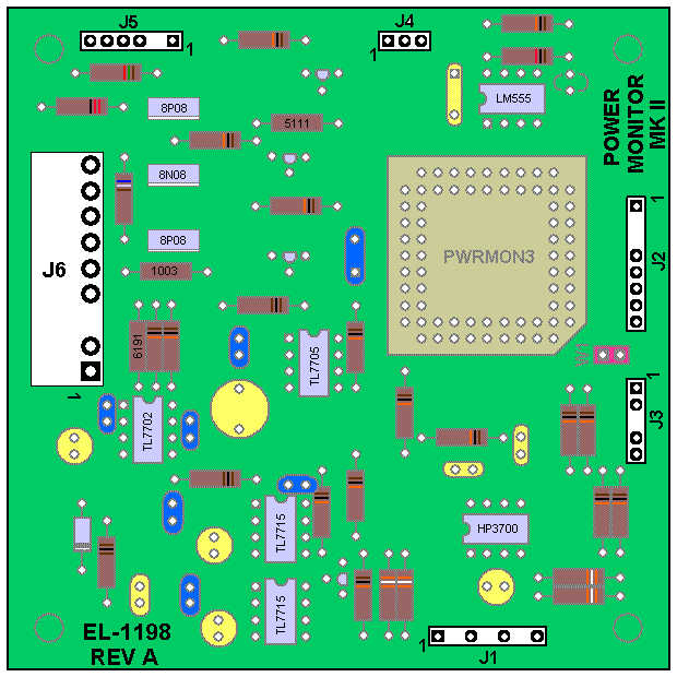
Wiring:
J1
120V AC is routed from the AC terminal strip and applied to pins 1 and 7 of the input connector J1. These are a black and white twisted pair that connects to terminals 2 and 5 of the AC terminal strip.
J2
Signals to and from the Utility Support board are wired to J2. The 16ENAB, 38ENAB, and the ANALOG SW EN REQ signals are inputs to the Power Monitor board. The EXRES signal is an output from the Power Monitor board. The +5 volt and ground lines are sent from the Power Monitor board to the Utility Support board to provide power for the opto-isolators for these signals. The connectors are keyed, 8-pin, 0.1" spacing, 'brown Molex' connectors using individual 22 AWG wire. The wire colors follow standard electronics color coding i.e. 1-brown, 2-red, etc. One note on this connector, for backward compatibility, the ANALOG SW EN REQ input has a associated jumper to allow for forcing the input on the Altera chip to be low. This enables the ANALOG SW EN REQ for older CCD controllers that do not provide this signal. All of the newer SDSU2 systems and most of the older SDSU1 systems do provide this signal and the jumper should be left off of the board.
J3
Contains the front panel 16V ENABLE and 38V ENABLE signals. These are twisted pairs that are soldered to the lugs on the switches and terminate into a 5-pin, 0.1" spacing, 'Black Molex' connector. The connector is keyed at pin 3. For testing purposes, the connector is marked on the left side as 34V and on the right side as 15V. This allows us to use jumper blocks to emulate the switches.
J4
The ANAL SW ENABLE is the output signal used to enable the analog switches. The connector is laid out so the connector can be put on in either orientation with the signal on the center pin and grounds on the outside pins of the 3-pin connector. Because this board is backward compatible with older versions of the CCD controllers, this signal is on it's own connector.
J5
This connector provides the wiring for the front panel power indicator LEDs. A 6-pin 'Black Molex' type connector is used for this wiring. The connector is keyed at pin 3 and twisted pair wire is used. At the front panel the LEDs are hard wired to these pairs.
J6
This connector contains the +5V, +/-16V, and +38V power wires. In each case, the wires from the power supply terminal strip are twisted with its ground wire. The only ground wire that connects to the board is the one twisted with the +5V. For the other voltages, the supply wire is twisted with it's ground until it gets to the Power Monitor connector. At that point, the ground wire continues and is then twisted with the switched supply line.