
| DEIMOS Slitmasks |
|
19 JAN 2007: NB: Priority_Codes must be non-zero for valid target objects! Some observers have had a problem with non-milled slits due to using Priority_Code=0 for program objects. DSimulator will incorrectly allow these objects to be selected, and, once selected, will design slits for them, but the slits will not be milled!
Think of Priority_Code as the weight of the object for selection, so zero weight [should] mean no target. This "feature" in the code will be fixed, but observers should NOT use Priority_Code=0 unless they really inderstand what it is for.
30 JAN 2004: A serious DSIMULATOR BUG has been reported by Gyula Szokoly (and confirmed). Contrary to the documentation, the normal mode of input will ignore variable slit width and always use the default instead. This will be fixed in the next release.
18 Dec 2002: Instructions for relinking the deimos package are now available. Also, in porting the package to a MacOSX system, I have found several small bugs which may cause problems on Linux systems (but I haven't heard of any such problems); these will all be fixed in the next release.
24 Sept 2002: Anyone who picked up Rev 0b between Sep 20 and Sep 23 should re-install it; there were two map files which were not updated, so the guider astrometry was old, not updated as advertised!
20 Sept 2002: The next mini-release is now available (Rev 0b); it contains several small extensions. The only modification to results is that the guider astrometry offsets are now included. Also note that the Linux version was compiled under RedHat 7.x (7.2?). Main changes:
Update (26Aug2002): NB! The TV astrometry in the mask-design code is NO LONGER CORRECT as the DEIMOS PXL camera was moved during repairs. Alison Coil reports that offsets of +2 X and +19 Y are needed.
Update (21Aug2002): First modified release (Redhat Linux 6.1 included) is now available. Follow instructions below.
ftp ftp.ucolick.org		# login anonymous
cd pub/users/phillips
binary
get deimos_rev0b.tar
quit
tar -xvf <tarfile>
setenv deimos /<path...>/deimos/You may need to source the file in order to get the environment variable set.
set deimos = "/<path...>/deimos/"
task deimos = deimos$deimos.cl
cl> deimosYou should see several tasks, the first of which is dsimulator. Typing "dsim" should give you a prompt for input file name, and you should be able to "epar dsim". At this point all should be ready.
DEIMOS slit masks will be milled at UCO/Lick for the duration of the shared-risk period, and possibly for a short time beyond. We are still experimenting with the optimal way to fabricate these masks. In addition, the mask-design and alignment tools are not yet finished at the level we would like them to be.
Planning: The Lick shops ask that they be given no more than 6 masks
per day for milling. Thus, please plan on 1 weeks + N/6 working days (M-F),
where N=number of masks, at a minimum. The Shops have also requested
a minimum of 2 weeks (if this is more than the previous equation) unless
special arrangements have been made in advance. This allows the Shops
time to schedule the mill, fabricate the masks, and Fedex the masks to Hawaii
in time for the run.
Second, there is a minimum slit width that can be milled with a given endmill. Due to various limitations, the shops strongly prefer to use 0.015-inch-diam ("15 thou") endmills. As the plate scale is 0.728 mm/arcsec, this places an absolute minimum of 0.524 arcsec on the available slitwidth; however, if tilted slits are used, the minimum in the dispersion direction is inreased by 1./cos(theta), where theta is the PA difference of the slit wrt the mask PA.
In addition, it is good to bear in mind that the slitlets are actually milled in a multi-pass manner at present, producing a relieved pocket around each slitlet, and allowing a clean-up cut to be made along the edge of each slitlet. The width of that clean-up cut must be factored into the effective endmill diameter if the user wishes it to be made (strongly advised); this width is currently set to 0.038 mm (each side), so the effective diameter of the endmill is 20% larger.
Requests for endmills other than the preferred (15 thou) size requires code development and debugging and such requests will only be accepted by special arrangement.
|
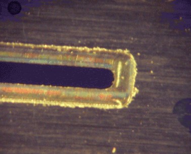
Magnified view of DEIMOS slitlet, showing actual slitlet and relieved pocket. The pocket is cut without an additional cleanup cut, and thus is significantly rougher than the actual slitlet cut. The slitlet in this case was cut (experimentally) with a 12-thou endmill, and is 0.6 arcsec wide. |
|
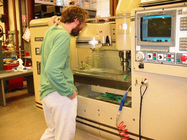
Steve Allen watches a DEIMOS slitmask being milled at the UCO/Lick shops. |
|
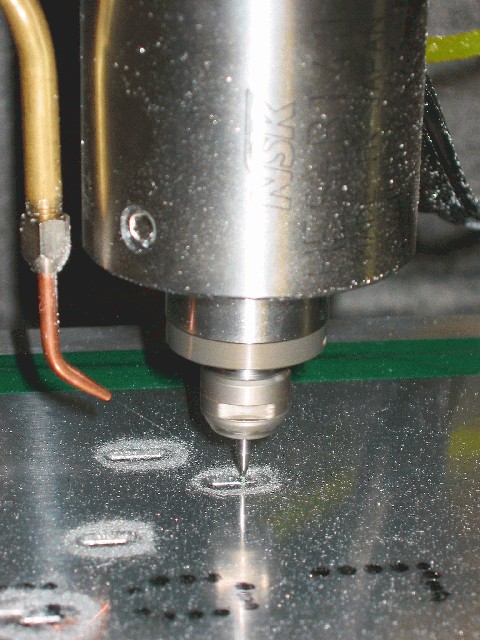
Closeup of the high-speed mill cutting slitlets. |
    objfile = "t1103.sim"     input file of targets
     output = "draco1.list"   output list selected/non-selected
        mdf = "draco1.fits    Mask Design File (FITS)
  (plotfile = "draco.mng")    (opt) plotfile [Mongo commands]
       (ra0 = 0.005)          Initial RA of field (hr)
      (dec0 = 0.)             Initial Dec of field (deg)
       (PA0 = 180.)           Initial PA of field (deg)
   (equinox = 2000.)          Equinox of coordinates
       (ha0 = -1.5)           Initial Hour Angle (hr)
  (min_slit = 8.)             Minimum slit length (arcsec)
  (sep_slit = 0.5)            Separation between slits (arcsec)
(slit_width = 0.75)           Width of slit (arcsec)
    (box_sz = 4.)             Alignment box size (arcsec)
      (blue = 5000.)          Shortest wavelength of interest [NOT USED]
       (red = 9000.)          Longest wavelength of interest [NOT USED]
  (proj_len = no)             Project slit length to preserve in spatial directi
(no_overlap = yes)            Adjust slit lengths to avoid overlap? (YES)
(std_format = yes)            Is input standard text format?
(lambda_cen = 7500.)          wavelength for refraction
      (temp = 0.)             Air temp (C)
  (pressure = 620.)           Air pressure (millibars==hPa)
    (author = "Drew Phillips <acp@ucolick.org>") Designer of Mask (name <email>)
  (observer = "Sandy Faber <smf@ucolick.org>")   Observer (name <email>)
   (project = "Astrometry--Commissioning")       Project name
    (maskid = "Draco_Astrometry_1")              Full Name of Mask
   (guiname = "DRACO1")       Name of Mask for GUI (6 char or less, no whitespace)
   (dateobs = "2002-07-03")   Date of intended use (YYYY-MM-DD)
ra0, dec0, equinox and PA0 may be entered via the input file (see below).
Required Fields:
(NB: Program objects should have PCODE > 0. There is a bug/feature that
currently allows slits
to be put over PCODE=0 objects, if no others are available in the area for
selection, but these slits will not be milled. This will be fixed, but in the
meantime users should avoid using PCODE=0, or should carefully check that
the results are as expected.)
Optional Fields (order is important):
There is currently no plan to calculate proper motion in the mask design tool.
Optional field center line: RA, Dec, standard_equinox and PA for the overall mask may be entered as the first non-commented line of the input file, provided it is of the form:
Name RA Dec Equinox PA=xxxxThe "PA=" is required to identify this unique entry, and cannot be followed by whitespace. Notice that "Name" on this line is ignored. The coordinates refer to the mask center, defined at x=0 and y=4.5 arcmin from the telescope center.
(In designing masks, we recommend identifying suitable alignment and guide stars and pre-selecting them in the input list.)
Alignment software (xbox) for DEIMOS has been tested and is being installed at Keck. Note that we have seen somewhat slow convergence during alignments, which we believe has to do with telescope pointing errors during small offsets. This is currently under investigation. However, there is some anecdotal evidence that _brighter_ guide stars make this process more secure. If you can put a star with R=16 on the guider mirror, do it! Also, note that there is significant vignetting in the guide camera away from the center, and that the light reflected off the slitmask is significantly less than that reflected off the guider mirror.
To aid the alignment process, the slit-mask design tool outputs the
expected guider coordinates of any object labeled "guide_star". These should
be noted and brought to the telescope. [Currently needs updated mapping;
astrometric analysis in progress.]
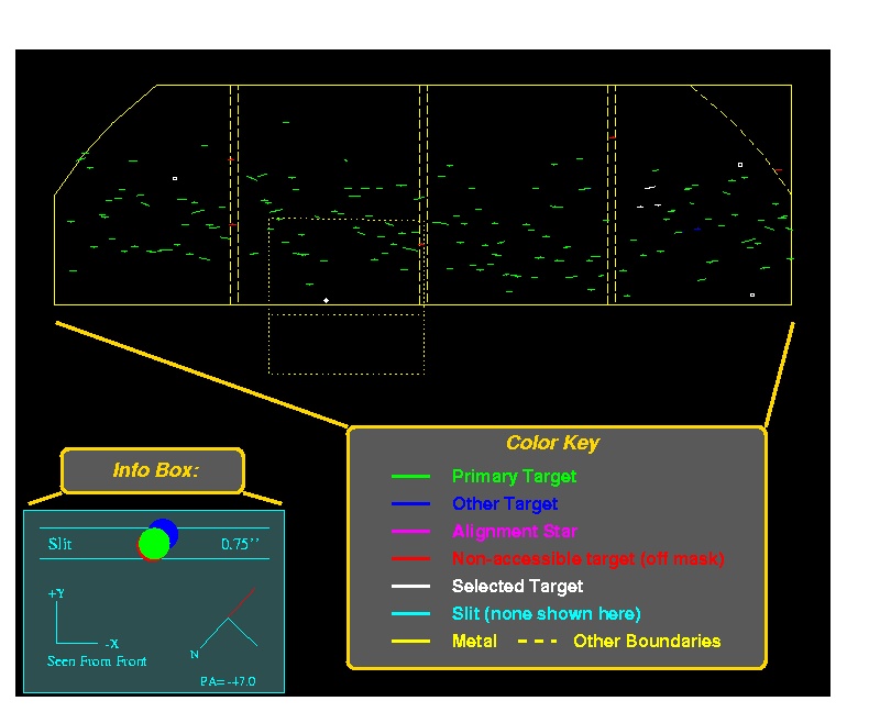
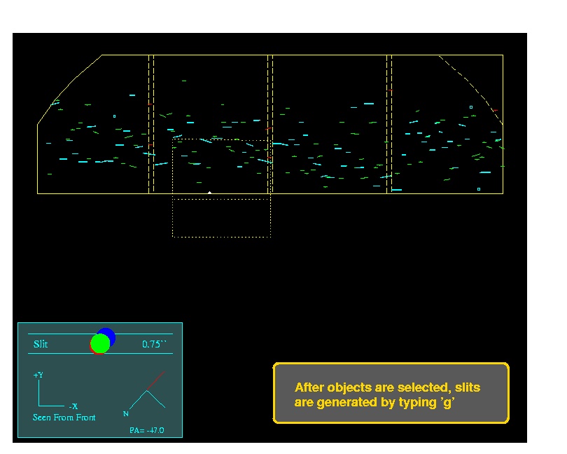
When dsimulator is invoked, the target list is read in and the targets are
displayed over a mask outline. Various colors are used to denote different
target classes and states:
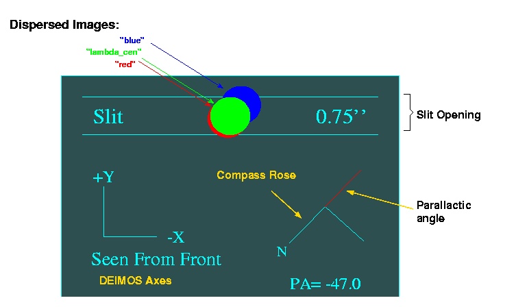
Also, note the information box. In addition to the standard DEIMOS axes
and a compass rose, there is a section of slit (with default slit-width)
shown along with a "dispersed" image, at min, central and max wavelengths.
For convenience, the seeing disk plotted is the same as the slit-width.
This information is useful for deciding acceptable mask PAs to avoid large
slit-losses from atmospheric dispersion:
Keystrokes are used for positioning the mask; adding, deleting and
auto-selecting targets; and generating slits. To see available options,
type '?':
[09Aug: I will try to give more details on these keystroke commands
shortly...]
In normal operation, the user first positions the mask on the sky using the
translation commands (h j k l, in the usual vi sense, to move the mask
on the sky) and rotation commands (p n, for position and negative
rotations). The size of these moves is controlled by '.', which cycles
through fast/medium/slow speeds (ie, large, medium, small steps).
Next, an "auto-select" ('s') is usually done, as this will try to maximize
the sum of the object priorities without creating any overlap conflicts.
The user may add ('a') or delete ('d') targets. "Space bar" will print
information about the target nearest the cursor. Also useful here is
the 'z' command, which replots the data centered on the cursor with the
absolute zoom factor specified. There are also some special values
defined: zoom_factor = 0 replots at normal scale; -1, -2, -3, -4 and -5
zoom in on the sections for CCDs 1, 2, 3, 4 and the TV field, respectively.
The standard plot buffer commands, such as Z, P, E, etc are also useful.
Make sure that alignment stars and at least one suitable guide star are
selected!
When the target selection is made, type 'g' to generate the slits, which
will be overplotted in cyan:
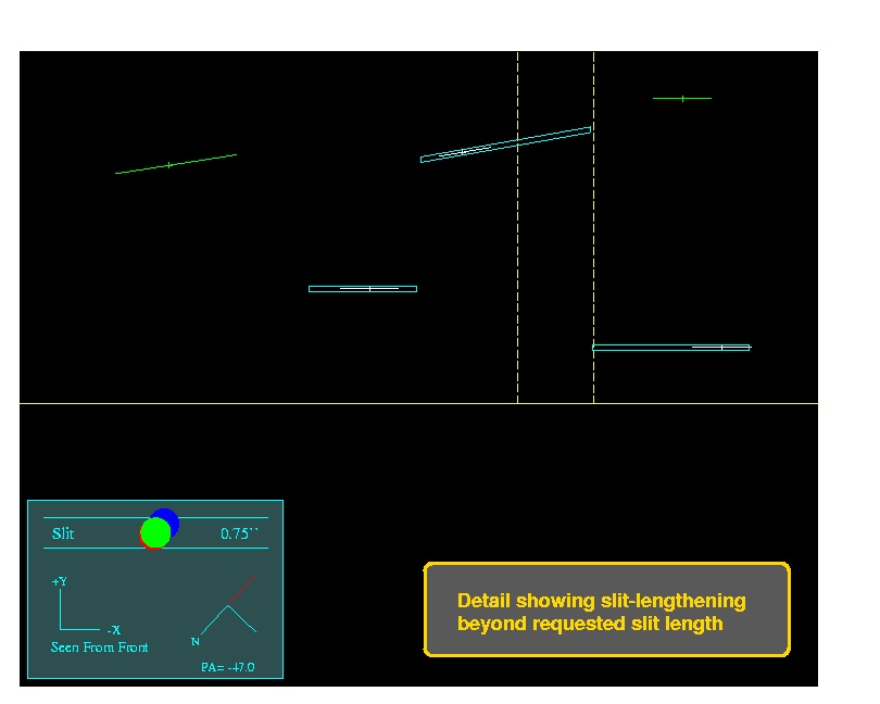
By default, slits are lengthened to where they nearly touch each other
(the slit separation is a parameter, for which 0.5 arcsec is currently
recommended). In cases where overlap would occur, by default the slits
are shortened to avoid overlap. In the plots, both the object (drawn
to show the requested slit length) and the slit appear, so it is immediately
apparent whether slits have been lengthened or truncated.
You can add and delete objects after slits have been generated; just do
another 'g' after the desired modifications. Note that all selected
objects will be given a slit, but slits may be badly truncated for objects
very close to one another. Also, avoid allowing slits to be lengthened
too much (say over 100 arcsec) -- really long slits may weaken the mask
and cause a jam upon insertion. In these cases, it is best to create
some new targets in empty regions and add them to the input list; these can be
randomly-placed sky slits.
The final step is 'q' to quit, at which point the MDF FITS file is generated,
as well as the output text file and the
optional plot file.
Note that the output text file has four sections:
These are all (* the TV section is commented out) in the same format required
for input, so it is easy for the user to, eg, contruct new input lists with only
objects that have not been selected. The first object is recognized
as the field center if it has a field "PA=nnn" in place of
magnitude. Note that this line is also properly formated for the Keck starlist,
provided the colons are replaced with spaces.
In brief, select the MDF to be submitted and hit "Send"; then hit "Sanity"
and the file will be checked for any syntax errors -- there should be none,
and you will see "ALL IS WELL" printed toward the bottom. Then hit "Ingest"
to place the file's information into the database. You must go through
all these steps; it's currently a bit painful but we are working on
streamlining it.
NB: All mask authors, observers and submitters must be recognized by
the database -- you must go to the above link and "introduce" yourself (and
relevant others) before attempting to submit MDFs. This is a one-time
effort. Also, access to the mask submission pages is only granted to
approved sites/networks. Even after you have registered as a mask user,
you will not be able to access the mask submission pages from any random
host -- only from hosts on approved networks. To request that your home
institution be added to the list of approved networks (if it is not
one already), send mail to slitmasks@ucolick.org.
Slitmask status and inventory can be monitored through the same URL.
Andrew C. Phillips / Lick Observatory
** Current limitations of DSIMULATOR
There are several shortcomings to the early release version. These include:
** Running DSIMULATOR
I strongly recommend that DSIMULATOR be run on an xgterm, and that the
window be expanded as large as feasible.
DSIMULATOR Command Summary:

     hjkl     translate mask (1" x speed) in the usual vi ways
     p/n      rotate mask (1 deg x speed) in a Pos/Neg sense
      .       cycle through speeds (10, 1, 0.1) for pnhjkl keys
      z       zoom (by abs factor; also 0 reset, -1,...,-5 for CCD1-4,TV fields)
      a       Add a target
      d       Delete a target
      r       Redraw
      i       Clear (initialize) the list of ALL selected objects
      s       Select workable set of objects
      g       generate slits to go over selected targets.
   <space>    print input line of nearest object
      ?       print this list
      q       quit
      I       interrupt task immediately
** Known Bugs
I'll attempt to keep this list current; please, please report bugs
to me at phillips@ucolick.org -- thanks!
Mask Design Submission
Mask-Design-Files (MDFs) are currently submitted via a
Web Form.
Masks will be milled automatically after they are successfully ingested in the
database. This path is currently under development; although it is working,
there are a few rough corners.
Tracking Your Masks
As noted above, slitmask fabrication status can be monitored using the
Web Form.
Once barcodes are assigned, you can verify they have been shipped from
UCO/Lick and received at Keck via the following site:
http://loen.ucolick.org/Deimos/shipping_log_index.htm
Observer Checklist
This is not a comprehensive checklist for designing slitmasks,
but rather items that are of crucial importance for success at the telescope.
de>  concat *<output_files> | match "PA=" > starlist
de>  edit starlist
or in UNIX:
>  cat *<output_files> | grep "PA=" > starlist
>  vi starlist
Then copy this file to your Keck account. (Doing this operation precludes
transcription errors in making the starlist.)
Date: Wed, 7 Aug 2002 14:26:50 -0700
From: Steve Allen
Last modified: 19jan2007